Information injection-pump assembly
ZEXEL
101601-9753
1016019753
Rating:
Cross reference number
ZEXEL
101601-9753
1016019753
Zexel num
Bosch num
Firm num
Name
101601-9753
INJECTION-PUMP ASSEMBLY
Calibration Data:
Adjustment conditions
Test oil
1404 Test oil ISO4113 or {SAEJ967d}
1404 Test oil ISO4113 or {SAEJ967d}
Test oil temperature
degC
40
40
45
Nozzle and nozzle holder
105780-8140
Bosch type code
EF8511/9A
Nozzle
105780-0000
Bosch type code
DN12SD12T
Nozzle holder
105780-2080
Bosch type code
EF8511/9
Opening pressure
MPa
17.2
Opening pressure
kgf/cm2
175
Injection pipe
Outer diameter - inner diameter - length (mm) mm 6-2-600
Outer diameter - inner diameter - length (mm) mm 6-2-600
Overflow valve
131424-1520
Overflow valve opening pressure
kPa
157
123
191
Overflow valve opening pressure
kgf/cm2
1.6
1.25
1.95
Tester oil delivery pressure
kPa
157
157
157
Tester oil delivery pressure
kgf/cm2
1.6
1.6
1.6
Direction of rotation (viewed from drive side)
Left L
Left L
Injection timing adjustment
Direction of rotation (viewed from drive side)
Left L
Left L
Injection order
1-5-3-6-
2-4
Pre-stroke
mm
3.3
3.25
3.35
Beginning of injection position
Drive side NO.1
Drive side NO.1
Difference between angles 1
Cal 1-5 deg. 60 59.5 60.5
Cal 1-5 deg. 60 59.5 60.5
Difference between angles 2
Cal 1-3 deg. 120 119.5 120.5
Cal 1-3 deg. 120 119.5 120.5
Difference between angles 3
Cal 1-6 deg. 180 179.5 180.5
Cal 1-6 deg. 180 179.5 180.5
Difference between angles 4
Cyl.1-2 deg. 240 239.5 240.5
Cyl.1-2 deg. 240 239.5 240.5
Difference between angles 5
Cal 1-4 deg. 300 299.5 300.5
Cal 1-4 deg. 300 299.5 300.5
Injection quantity adjustment
Adjusting point
A
Rack position
10.2
Pump speed
r/min
1450
1450
1450
Average injection quantity
mm3/st.
61
59
63
Max. variation between cylinders
%
0
-3
3
Basic
*
Fixing the lever
*
Injection quantity adjustment_02
Adjusting point
C
Rack position
9.1+-0.5
Pump speed
r/min
250
250
250
Average injection quantity
mm3/st.
10
8.5
11.5
Max. variation between cylinders
%
0
-15
15
Fixing the lever
*
Injection quantity adjustment_03
Adjusting point
D
Rack position
-
Pump speed
r/min
100
100
100
Average injection quantity
mm3/st.
72
72
Fixing the lever
*
Remarks
After startup boost setting
After startup boost setting
Timer adjustment
Pump speed
r/min
550--
Advance angle
deg.
0
0
0
Remarks
Start
Start
Timer adjustment_02
Pump speed
r/min
500
Advance angle
deg.
0.5
Timer adjustment_03
Pump speed
r/min
1000
Advance angle
deg.
3.2
2.7
3.7
Timer adjustment_04
Pump speed
r/min
1500
Advance angle
deg.
6.5
6
7
Remarks
Finish
Finish
Test data Ex:
Governor adjustment
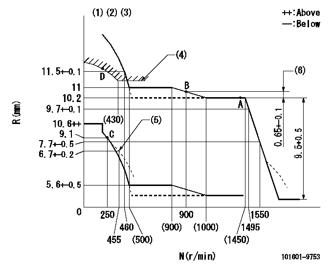
N:Pump speed
R:Rack position (mm)
(1)Lever ratio: RT
(2)Target shim dimension: TH
(3)Tolerance for racks not indicated: +-0.05mm.
(4)Excess fuel setting for starting: SXL (N = N1)
(5)Damper spring setting
(6)Rack difference to N = N2
----------
RT=1 TH=2.2mm SXL=11.1+0.2mm N1=450r/min N2=1450r/min
----------
----------
RT=1 TH=2.2mm SXL=11.1+0.2mm N1=450r/min N2=1450r/min
----------
Speed control lever angle

F:Full speed
----------
----------
a=19deg+-5deg
----------
----------
a=19deg+-5deg
0000000901
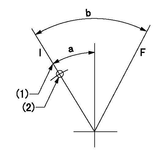
F:Full load
I:Idle
(1)Stopper bolt setting
(2)Use the hole at R = aa
----------
aa=55mm
----------
a=5.5deg+-5deg b=20deg+-3deg
----------
aa=55mm
----------
a=5.5deg+-5deg b=20deg+-3deg
Stop lever angle
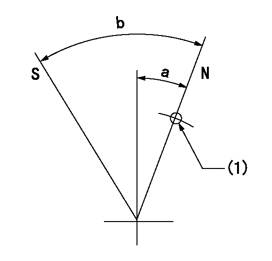
N:Pump normal
S:Stop the pump.
(1)Use the pin at R = aa
----------
aa=30mm
----------
a=35deg+-5deg b=71deg+-5deg
----------
aa=30mm
----------
a=35deg+-5deg b=71deg+-5deg
Timing setting

(1)Pump vertical direction
(2)Coupling's key groove position for the No. 6 cylinder's beginning of injection
(3)-
(4)-
----------
----------
a=(30deg)
----------
----------
a=(30deg)
Information:
This is a 5.0-hour job
PARTS DISPOSITION
Handle the parts in accordance with your Warranty Bulletin on warranty parts handling.
Rework Procedure
Make sure you have read and understood all of this document before beginning work.
Isolate the generator set before commencing any work on the unit, open generator set breaker, activate Emergency Stop, disconnect the battery cables and either disconnect or open the control circuit breaker for the AC power supply to the battery charger. Ensure all health and safety requirements are adhered to at all times. Also, ensure proper Lock Out-Tag Out procedures are followed at all times while work is being performed on or around the machine. Lock out generator operation and disconnect/lockout all power sources before commencing any work.
1 - Remove the SCR (selective catalyst reduction) side heat shields in order to gain access to the SCR cover. Remove all of the bolts, plates & SCR cover panel. Clean the old gasket material from the Clean Emission Module (CEM) & SCR cover panels.
Reference Image 1.2.1
Image1.2.1
2 - With a new gasket (351-9235) install the SCR cover panel (351-6791), backing plates (351-6794 & 351-6795), washers (7X7729) and original M10 bolts (8T4182) onto the CEM in the following locations:
(7) top center holes
(7) bottom center holes
(1) LH middle hole
(1) RH middle hole
Hand tighten these bolts.
On each corner install a 1" thick plate (512-8186) with (2) washers (7X7729) and (2) longer M10 bolts (8T5005).
Hand tighten these bolts.
Install a nut (5P7970 onto
Have questions with 101601-9753?
Group cross 101601-9753 ZEXEL
101601-9753
INJECTION-PUMP ASSEMBLY