Information injection-pump assembly
ZEXEL
101601-9712
1016019712
Rating:
Cross reference number
ZEXEL
101601-9712
1016019712
Zexel num
Bosch num
Firm num
Name
Calibration Data:
Adjustment conditions
Test oil
1404 Test oil ISO4113 or {SAEJ967d}
1404 Test oil ISO4113 or {SAEJ967d}
Test oil temperature
degC
40
40
45
Nozzle and nozzle holder
105780-8140
Bosch type code
EF8511/9A
Nozzle
105780-0000
Bosch type code
DN12SD12T
Nozzle holder
105780-2080
Bosch type code
EF8511/9
Opening pressure
MPa
17.2
Opening pressure
kgf/cm2
175
Injection pipe
Outer diameter - inner diameter - length (mm) mm 6-2-600
Outer diameter - inner diameter - length (mm) mm 6-2-600
Overflow valve opening pressure
kPa
157
123
191
Overflow valve opening pressure
kgf/cm2
1.6
1.25
1.95
Tester oil delivery pressure
kPa
157
157
157
Tester oil delivery pressure
kgf/cm2
1.6
1.6
1.6
Direction of rotation (viewed from drive side)
Right R
Right R
Injection timing adjustment
Direction of rotation (viewed from drive side)
Right R
Right R
Injection order
1-4-2-6-
3-5
Pre-stroke
mm
3.4
3.35
3.45
Beginning of injection position
Drive side NO.1
Drive side NO.1
Difference between angles 1
Cal 1-4 deg. 60 59.5 60.5
Cal 1-4 deg. 60 59.5 60.5
Difference between angles 2
Cyl.1-2 deg. 120 119.5 120.5
Cyl.1-2 deg. 120 119.5 120.5
Difference between angles 3
Cal 1-6 deg. 180 179.5 180.5
Cal 1-6 deg. 180 179.5 180.5
Difference between angles 4
Cal 1-3 deg. 240 239.5 240.5
Cal 1-3 deg. 240 239.5 240.5
Difference between angles 5
Cal 1-5 deg. 300 299.5 300.5
Cal 1-5 deg. 300 299.5 300.5
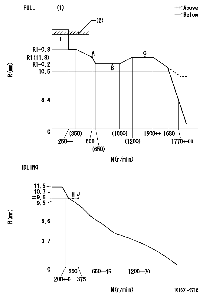
Injection quantity adjustment
Adjusting point
-
Rack position
11.8
Pump speed
r/min
600
600
600
Average injection quantity
mm3/st.
66.3
64.7
67.9
Max. variation between cylinders
%
0
-3.5
3.5
Basic
*
Fixing the rack
*
Standard for adjustment of the maximum variation between cylinders
*
Injection quantity adjustment_02
Adjusting point
H
Rack position
9.5+-0.5
Pump speed
r/min
300
300
300
Average injection quantity
mm3/st.
9.5
7.7
11.3
Max. variation between cylinders
%
0
-10
10
Fixing the rack
*
Standard for adjustment of the maximum variation between cylinders
*
Injection quantity adjustment_03
Adjusting point
A
Rack position
R1(11.8)
Pump speed
r/min
600
600
600
Average injection quantity
mm3/st.
66.3
65.3
67.3
Basic
*
Fixing the lever
*
Injection quantity adjustment_04
Adjusting point
B
Rack position
R1-0.2
Pump speed
r/min
900
900
900
Average injection quantity
mm3/st.
73
69.8
76.2
Fixing the lever
*
Injection quantity adjustment_05
Adjusting point
C
Rack position
R1(11.8)
Pump speed
r/min
1500
1500
1500
Average injection quantity
mm3/st.
83.9
79.9
87.9
Fixing the lever
*
Injection quantity adjustment_06
Adjusting point
I
Rack position
-
Pump speed
r/min
100
100
100
Average injection quantity
mm3/st.
84
84
94
Fixing the lever
*
Rack limit
*
Test data Ex:
Governor adjustment
N:Pump speed
R:Rack position (mm)
(1)Torque cam stamping: T1
(2)RACK LIMIT
----------
T1=B55
----------
----------
T1=B55
----------
Timer adjustment
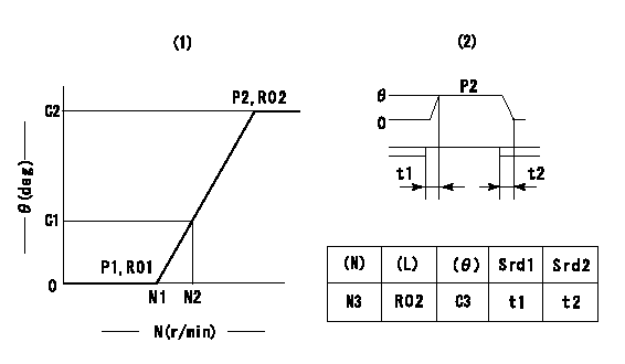
(1)Adjusting range
(2)Step response time
(N): Speed of the pump
(L): Load
(theta) Advance angle
(Srd1) Step response time 1
(Srd2) Step response time 2
1. Adjusting conditions for the variable timer
(1)Adjust the clearance between the pickup and the protrusion to L.
----------
L=1.5+-0.2mm N3=800r/min C3=(6.5deg) t1=2--sec. t2=2--sec.
----------
N1=1200++r/min N2=1400r/min P1=0kPa(0kgf/cm2) P2=392kPa(4kgf/cm2) C1=2.5--deg C2=6.5+-0.4deg R01=0/4load R02=4/4load
----------
L=1.5+-0.2mm N3=800r/min C3=(6.5deg) t1=2--sec. t2=2--sec.
----------
N1=1200++r/min N2=1400r/min P1=0kPa(0kgf/cm2) P2=392kPa(4kgf/cm2) C1=2.5--deg C2=6.5+-0.4deg R01=0/4load R02=4/4load
Speed control lever angle

F:Full speed
I:Idle
(1)Stopper bolt set position 'H'
----------
----------
a=26.5deg+-5deg b=40deg+-3deg
----------
----------
a=26.5deg+-5deg b=40deg+-3deg
Stop lever angle

N:Pump normal
S:Stop the pump.
----------
----------
a=20deg+-5deg b=40deg+-5deg
----------
----------
a=20deg+-5deg b=40deg+-5deg
0000001501 RACK SENSOR
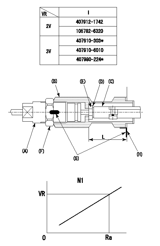
(VR) measurement voltage
(I) Part number of the control unit
(G) Apply red paint.
(H): End surface of the pump
1. Rack limit adjustment
(1)Fix the rack at the rack limit position Ra.
(2)Install the shim (D) to the rod (C) and tighten nut (E).
(3)Select a shim (D) so that the distance between the end surface of the pump and the nut (E) is L.
(4)Release the rack fixing and mount the joint (B) and fix.
(5)At this time, confirm that the shim (D) does not interfere with the joint (B).
2. Rack sensor adjustment (-0420)
(1)Screw in the bobbin (A) until it contacts the joint (B).
(2)Fix the speed control lever at the full side.
(3)Set the speed to N1 r/min.
(4)Adjust the depth that the bobbin (A) is screwed in so that the control unit's rack sensor output voltage is VR+-0.01 (V), then tighten the nut (F).
(5)Adjust the bobbin (A) so that the rack sensor's output voltage is VR.
(6)Apply G at two places.
Connecting part between the joint (B) and the nut (F)
Connecting part between the joint (B) and the end surface of the pump (H)
----------
L=33-0.2mm N1=600r/min Ra=R1(11.8)mm
----------
----------
L=33-0.2mm N1=600r/min Ra=R1(11.8)mm
----------
Timing setting

(1)Pump vertical direction
(2)Position of timer's threaded hole at No 1 cylinder's beginning of injection
(3)B.T.D.C.: aa
(4)-
----------
aa=11deg
----------
a=(60deg)
----------
aa=11deg
----------
a=(60deg)
Information:
Model Identification Number
AFTERTREAT-SCR ES700101, 105-170, 231-259, 266-273
PARTS NEEDED
Qty
Part Number Description
1 4487104 DISC-SUPPORT
In order to allow equitable parts availability to all participating dealers, please limit your initial parts order to not exceed 32% of dealership population. This is an initial order recommendation only, and the ultimate responsibility for ordering the total number of parts needed to satisfy the program lies with the dealer.
ACTION REQUIRED
Prior to Disassembly:
Remove/Turn off all power to the dosing cabinet.
Lock Out and Tag Out the master disconnect.
Follow all mandated safety rules.
Please refer to the attached Rework Procedure.
SERVICE CLAIM ALLOWANCES
Product smu/age whichever comes first Caterpillar Dealer Suggested Customer Suggested
Parts % Labor Hrs% Parts % Labor Hrs% Parts % Labor Hrs%
0-8000 hrs,
0-24 mo 100.0% 100.0% 0.0% 0.0% 0.0% 0.0%
This is a 2.0-hour job
PARTS DISPOSITION
Handle the parts in accordance with your Warranty Bulletin on warranty parts handling.
Rework Procedure
Early production dosing cabinets under went several changes with the Diesel Exhaust Fluid Back Pressure Valves that were installed at the factory. (A) Plastic Housing, (B) Stainless Steel Housing, and (C) Stainless Steel Body with Plastic Cap. Refer Image 1.1.1.
Identify the Diesel Exhaust Fluid Back Pressure Valve in the dosing cabinet, and proceed to the appropriate rework procedure below.
Remove the Diesel Exhaust Fluid Back Pressure Valve from dosing cabinet. Refer to Image 1.1.2.
Disassemble and replace the internal support disc. Refer to Image 1.1.3.
Reassemble valve and tighten the assembly screws 5 Nm ( 43 in lb ). Reinstall valve into dosing cabinet.
Once Diesel Exhaust Fluid Back Pressure Valve has been reinstalled, it is necessary
to set the back pressure valve at ~40 psi. This is an important adjustment. If the back pressure valve is set too low it will not be able to seal against the DEF head pressure, and can flood the reactor. If the valve is set two high, it can stop all flow of DEF, and will force DEF out the pump pressure release valve, possibly damaging the pump.
Procedure to Set Back Pressure Valve
Plastic Housing (A) or Stainless Steel Housing (B)
The field method of setting the valve is to back off the adjustment screw until the spring pressure is released, tighten the screw until contact is made with the spring, then tighten the screw two complete revolutions. The adjustment screw gives ~20 psi per revolution of the screw, so two turns sets it at about 40 psi.
Note: Special care should be taken when determining when the screw makes contact with the spring. Occasionally the screw can be tight, making it hard to determine when the screw makes contact with the spring. Lubricating the screw can help.
Stainless Steel Body with Plastic Cap (C)
The valve may be marked as BPM025SV50P. Refer to Image 1.1.4. If the spring has 9 coils (A), unscrew