Information injection-pump assembly
ZEXEL
101601-9610
1016019610
NISSAN-DIESEL
16713Z5610
16713z5610
Rating:
Cross reference number
ZEXEL
101601-9610
1016019610
NISSAN-DIESEL
16713Z5610
16713z5610
Zexel num
Bosch num
Firm num
Name
101601-9610
16713Z5610 NISSAN-DIESEL
INJECTION-PUMP ASSEMBLY
FD6 * K
FD6 * K
Calibration Data:
Adjustment conditions
Test oil
1404 Test oil ISO4113 or {SAEJ967d}
1404 Test oil ISO4113 or {SAEJ967d}
Test oil temperature
degC
40
40
45
Nozzle and nozzle holder
105780-8140
Bosch type code
EF8511/9A
Nozzle
105780-0000
Bosch type code
DN12SD12T
Nozzle holder
105780-2080
Bosch type code
EF8511/9
Opening pressure
MPa
17.2
Opening pressure
kgf/cm2
175
Injection pipe
Outer diameter - inner diameter - length (mm) mm 6-2-600
Outer diameter - inner diameter - length (mm) mm 6-2-600
Overflow valve
132424-0620
Overflow valve opening pressure
kPa
157
123
191
Overflow valve opening pressure
kgf/cm2
1.6
1.25
1.95
Tester oil delivery pressure
kPa
157
157
157
Tester oil delivery pressure
kgf/cm2
1.6
1.6
1.6
Direction of rotation (viewed from drive side)
Right R
Right R
Injection timing adjustment
Direction of rotation (viewed from drive side)
Right R
Right R
Injection order
1-4-2-6-
3-5
Pre-stroke
mm
3
2.95
3.05
Beginning of injection position
Drive side NO.1
Drive side NO.1
Difference between angles 1
Cal 1-4 deg. 60 59.5 60.5
Cal 1-4 deg. 60 59.5 60.5
Difference between angles 2
Cyl.1-2 deg. 120 119.5 120.5
Cyl.1-2 deg. 120 119.5 120.5
Difference between angles 3
Cal 1-6 deg. 180 179.5 180.5
Cal 1-6 deg. 180 179.5 180.5
Difference between angles 4
Cal 1-3 deg. 240 239.5 240.5
Cal 1-3 deg. 240 239.5 240.5
Difference between angles 5
Cal 1-5 deg. 300 299.5 300.5
Cal 1-5 deg. 300 299.5 300.5
Injection quantity adjustment
Adjusting point
-
Rack position
11.5
Pump speed
r/min
900
900
900
Average injection quantity
mm3/st.
54.7
53.1
56.3
Max. variation between cylinders
%
0
-2
2
Basic
*
Fixing the rack
*
Standard for adjustment of the maximum variation between cylinders
*
Injection quantity adjustment_02
Adjusting point
H
Rack position
9.5+-0.5
Pump speed
r/min
300
300
300
Average injection quantity
mm3/st.
8.2
6.4
10
Max. variation between cylinders
%
0
-12
12
Fixing the rack
*
Standard for adjustment of the maximum variation between cylinders
*
Injection quantity adjustment_03
Adjusting point
A
Rack position
R1(11.5)
Pump speed
r/min
900
900
900
Average injection quantity
mm3/st.
54.7
53.7
55.7
Basic
*
Fixing the lever
*
Injection quantity adjustment_04
Adjusting point
I
Rack position
14.5+-0.
5
Pump speed
r/min
150
150
150
Average injection quantity
mm3/st.
80
80
90
Fixing the lever
*
Rack limit
*
Timer adjustment
Pump speed
r/min
(1230)
Advance angle
deg.
0
0
0
Remarks
Start
Start
Timer adjustment_02
Pump speed
r/min
1500
Advance angle
deg.
4
3.5
4.5
Remarks
Finish
Finish
Test data Ex:
Governor adjustment
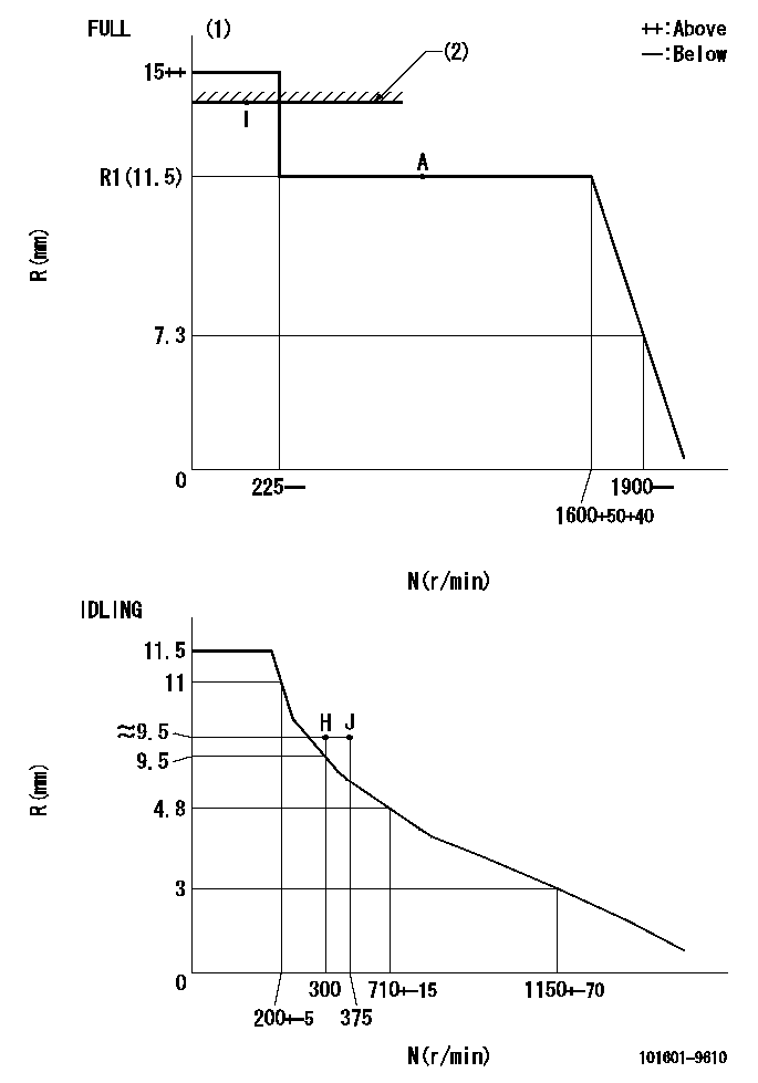
N:Pump speed
R:Rack position (mm)
(1)Torque cam stamping: none
(2)RACK LIMIT
----------
----------
----------
----------
Speed control lever angle

F:Full speed
I:Idle
(1)Stopper bolt set position 'H'
----------
----------
a=26.5deg+-5deg b=42deg+-3deg
----------
----------
a=26.5deg+-5deg b=42deg+-3deg
Stop lever angle

N:Pump normal
S:Stop the pump.
----------
----------
a=20deg+-5deg b=40deg+-5deg
----------
----------
a=20deg+-5deg b=40deg+-5deg
Timing setting

(1)Pump vertical direction
(2)Position of timer's threaded hole at No 1 cylinder's beginning of injection
(3)-
(4)-
----------
----------
a=(60deg)
----------
----------
a=(60deg)
Information:
Marks For Tightening Connecting Rod Bolts(1) Bore in connecting rod for piston pin bearing ... 55.035 0.013 mm (2.167 .0005 in) The connecting rod must be heated for installation of piston pin bearing. Do not use a torch.(2) Distance rod may be heated to 175 to 260°C (347 to 500°F) to install the piston pin bearing ... 85.0 mm (3.35 in)(3) Bore in bearing for piston pin (new) ... 55.047 .008 mm (2.1672 .0003 in) Diameter of piston pin (new) ... 55.000 .005 mm (2.1654 .0002 in)Thoroughly lubricate piston pin with clean engine oil prior to inserting into piston group and rod assembly. Maximum permissible clearance between bearing and piston pin (worn) ... 0.25 mm (.010 in)(4) Bearing joint must be assembled at either location on centerline through the connecting rod bore ... 5 degreesMake reference to Special Instruction, SMHS7295 for use of pin bearing removal and installation tools and procedures.(5) Distance between center of bearings ... 261.62 0.05 mm (10.300 .002 in)(6) Bore in connecting rod for bearing with nuts tightened to specifications (8) ... 96.200 0.013 mm (3.7874 .0005 in)(7) Location for etching cylinder number on connecting rod and cap. Rods and caps are to be marked with numbers 1 through 6 on the same side of the rod as the bearing tab slots.(8) Tighten connecting rod bolts as follows: a. Before installing bolts, lubricate bolt threads and seating faces of the caps with 4C5593 Thread Lubricant.b. Tighten each bolt to ... 90 9 N m (66 7 lb ft)c. Put an alignment mark on each cap and bolt.d. Tighten each bolt an additional ... 90 9 degrees (1/4 turn)(9) Bore in bearing for crankshaft rod journal ... 90.112 0.028 mm (3.5477 .0011 in) Clearance between bearing and crankshaft (new) ... 0.062 to 0.160 mm (.0024 to .0063 in)Maximum permissible clearance between bearing and crankshaft (worn) ... 0.20 mm (.008 in) Bearings are available in 0.63 mm (.025 in) and 1.27 mm (.050 in) smaller than original size.
Have questions with 101601-9610?
Group cross 101601-9610 ZEXEL
Nissan-Diesel
101601-9610
16713Z5610
INJECTION-PUMP ASSEMBLY
FD6
FD6