Information injection-pump assembly
ZEXEL
101601-9461
1016019461
Rating:
Service parts 101601-9461 INJECTION-PUMP ASSEMBLY:
1.
_
7.
COUPLING PLATE
8.
_
9.
_
10.
NOZZLE AND HOLDER ASSY
11.
Nozzle and Holder
12.
Open Pre:MPa(Kqf/cm2)
13.
NOZZLE-HOLDER
14.
NOZZLE
15.
NOZZLE SET
Cross reference number
ZEXEL
101601-9461
1016019461
Zexel num
Bosch num
Firm num
Name
101601-9461
INJECTION-PUMP ASSEMBLY
SX6130 *
SX6130 *
Calibration Data:
Adjustment conditions
Test oil
1404 Test oil ISO4113 or {SAEJ967d}
1404 Test oil ISO4113 or {SAEJ967d}
Test oil temperature
degC
40
40
45
Nozzle and nozzle holder
105780-8140
Bosch type code
EF8511/9A
Nozzle
105780-0000
Bosch type code
DN12SD12T
Nozzle holder
105780-2080
Bosch type code
EF8511/9
Opening pressure
MPa
17.2
Opening pressure
kgf/cm2
175
Injection pipe
Outer diameter - inner diameter - length (mm) mm 6-2-600
Outer diameter - inner diameter - length (mm) mm 6-2-600
Overflow valve
132424-0620
Overflow valve opening pressure
kPa
157
123
191
Overflow valve opening pressure
kgf/cm2
1.6
1.25
1.95
Tester oil delivery pressure
kPa
157
157
157
Tester oil delivery pressure
kgf/cm2
1.6
1.6
1.6
Direction of rotation (viewed from drive side)
Right R
Right R
Injection timing adjustment
Direction of rotation (viewed from drive side)
Right R
Right R
Injection order
1-5-3-6-
2-4
Pre-stroke
mm
1.95
1.9
2
Beginning of injection position
Drive side NO.1
Drive side NO.1
Difference between angles 1
Cal 1-5 deg. 60 59.5 60.5
Cal 1-5 deg. 60 59.5 60.5
Difference between angles 2
Cal 1-3 deg. 120 119.5 120.5
Cal 1-3 deg. 120 119.5 120.5
Difference between angles 3
Cal 1-6 deg. 180 179.5 180.5
Cal 1-6 deg. 180 179.5 180.5
Difference between angles 4
Cyl.1-2 deg. 240 239.5 240.5
Cyl.1-2 deg. 240 239.5 240.5
Difference between angles 5
Cal 1-4 deg. 300 299.5 300.5
Cal 1-4 deg. 300 299.5 300.5
Injection quantity adjustment
Adjusting point
A
Rack position
10.3
Pump speed
r/min
1000
1000
1000
Average injection quantity
mm3/st.
126
124
128
Max. variation between cylinders
%
0
-2.5
2.5
Basic
*
Fixing the lever
*
Injection quantity adjustment_02
Adjusting point
B
Rack position
6.1+-0.5
Pump speed
r/min
225
225
225
Average injection quantity
mm3/st.
15
13.5
16.5
Max. variation between cylinders
%
0
-15
15
Fixing the rack
*
Injection quantity adjustment_03
Adjusting point
C
Rack position
-
Pump speed
r/min
100
100
100
Average injection quantity
mm3/st.
140
140
Fixing the lever
*
Remarks
After startup boost setting
After startup boost setting
Timer adjustment
Pump speed
r/min
450--
Advance angle
deg.
0
0
0
Remarks
Start
Start
Timer adjustment_02
Pump speed
r/min
400
Advance angle
deg.
0.5
Timer adjustment_03
Pump speed
r/min
700
Advance angle
deg.
2.2
1.7
2.7
Timer adjustment_04
Pump speed
r/min
1000
Advance angle
deg.
6
5.5
6.5
Remarks
Finish
Finish
Test data Ex:
Governor adjustment
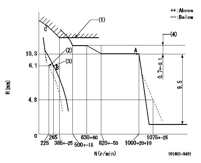
N:Pump speed
R:Rack position (mm)
(1)Excess fuel setting for starting: SXL
(2)Damper spring setting
(3)Set the main spring and the damper spring.
(4)Rack difference between N = N1 and N = N2
----------
SXL=11.1+0.2mm N1=1000r/min N2=600r/min
----------
----------
SXL=11.1+0.2mm N1=1000r/min N2=600r/min
----------
Speed control lever angle

F:Full speed
I:Idle
(1)Stopper bolt setting
----------
----------
a=5deg+-5deg b=19deg+-5deg
----------
----------
a=5deg+-5deg b=19deg+-5deg
0000000901
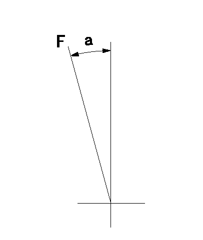
F:Full load
----------
----------
a=20deg+-5deg
----------
----------
a=20deg+-5deg
Stop lever angle

N:Pump normal
S:Stop the pump.
----------
----------
a=36deg+-5deg b=71deg+-5deg
----------
----------
a=36deg+-5deg b=71deg+-5deg
Timing setting

(1)Pump vertical direction
(2)Coupling's key groove position at No 1 cylinder's beginning of injection
(3)-
(4)-
----------
----------
a=(40deg)
----------
----------
a=(40deg)
Information:
Recommended Procedure With Chassis Dynamometer
Possible Causes/Corrections Minor Operating FaultsTo help identify a problem before a more involved troubleshooting procedure is started, follow the procedure given in the "Primary Engine Checks" section. Fuel Ratio Control Out Of Adjustment Or DefectiveFollow the procedure in the Testing and Adjusting Section of this Service Manual. Check Engine PerformanceDo a Power Analysis Report (PAR), Level II, to check engine performance. Refer to LEBV2810 and SEHS7886 for the tooling and procedures to use. Be sure to make a record of the temperatures for inlet air, fuel (at filter base), lubricating oil and coolant. Fuel Settings Not CorrectIf the Power Analysis Report indicates a problem, the governor fuel settings should be verified. See the Testing and Adjusting Section of this Service Manual for the necessary procedures. Also, refer back to the information learned earlier (see "Owner/Operator Input" section) about the truck specifications and application and judge whether or not the engine is performing as expected or customer expectation is realistic. Defective Fuel Nozzle(s)Remove the fuel nozzles and test as in the Testing and Adjusting Section of this Service Manual.Recommended Procedure Without Chassis Dynamometer
Possible Causes/Corrections Minor Operating FaultsTo help identify a problem before a more involved troubleshooting procedure is started, follow the procedure given in the "Primary Engine Checks" section. Fuel Ratio Control Out Of Adjustment Or DefectiveCheck engine timing with the 8T5300 Timing Indicator Group. Follow the procedure in the Testing and Adjusting Section of this Service Manual. Fuel Injection Timing Not CorrectFollow the procedures in the Testing and Adjusting Section of this Service Manual. Check Engine PerformanceInstall the tooling and follow the procedure given in the "Road Test" section. Fuel Settings Not CorrectIf the Road Test indicates a problem, the governor fuel settings should be verified. See the Testing and Adjusting Section of this Service Manual for the necessary procedures. Also, refer back to the information learned earlier (see "Owner Operator Input" section) about the truck specifications and application and judge whether or not the engine is performing as expected or customer expectation is realistic. Any Further Diagnosis Must Be Done On A Chassis DynamometerIf the fuel settings are correct and the above procedures have been followed without finding the problem a Power Analysis Report (PAR), Level II, must be done on the engine. Refer to LEBV2810 and SEHS7886 for the correct tools and procedures to use.
Have questions with 101601-9461?
Group cross 101601-9461 ZEXEL
Nissan-Diesel
101601-9461
INJECTION-PUMP ASSEMBLY
SX6130
SX6130