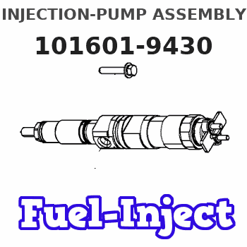
Information injection-pump assembly
ZEXEL
101601-9430
1016019430
Rating:
Cross reference number
ZEXEL
101601-9430
1016019430
Zexel num
Bosch num
Firm num
Name
Calibration Data:
Adjustment conditions
Test oil
1404 Test oil ISO4113 or {SAEJ967d}
1404 Test oil ISO4113 or {SAEJ967d}
Test oil temperature
degC
40
40
45
Nozzle and nozzle holder
105780-8140
Bosch type code
EF8511/9A
Nozzle
105780-0000
Bosch type code
DN12SD12T
Nozzle holder
105780-2080
Bosch type code
EF8511/9
Opening pressure
MPa
17.2
Opening pressure
kgf/cm2
175
Injection pipe
Outer diameter - inner diameter - length (mm) mm 6-2-600
Outer diameter - inner diameter - length (mm) mm 6-2-600
Overflow valve
132424-0620
Overflow valve opening pressure
kPa
157
123
191
Overflow valve opening pressure
kgf/cm2
1.6
1.25
1.95
Tester oil delivery pressure
kPa
157
157
157
Tester oil delivery pressure
kgf/cm2
1.6
1.6
1.6
Direction of rotation (viewed from drive side)
Right R
Right R
Injection timing adjustment
Direction of rotation (viewed from drive side)
Right R
Right R
Injection order
1-4-2-6-
3-5
Pre-stroke
mm
3
2.95
3.05
Beginning of injection position
Drive side NO.1
Drive side NO.1
Difference between angles 1
Cal 1-4 deg. 60 59.5 60.5
Cal 1-4 deg. 60 59.5 60.5
Difference between angles 2
Cyl.1-2 deg. 120 119.5 120.5
Cyl.1-2 deg. 120 119.5 120.5
Difference between angles 3
Cal 1-6 deg. 180 179.5 180.5
Cal 1-6 deg. 180 179.5 180.5
Difference between angles 4
Cal 1-3 deg. 240 239.5 240.5
Cal 1-3 deg. 240 239.5 240.5
Difference between angles 5
Cal 1-5 deg. 300 299.5 300.5
Cal 1-5 deg. 300 299.5 300.5
Injection quantity adjustment
Adjusting point
A
Rack position
9
Pump speed
r/min
900
900
900
Average injection quantity
mm3/st.
51.4
49.8
53
Max. variation between cylinders
%
0
-2
2
Basic
*
Fixing the lever
*
Injection quantity adjustment_02
Adjusting point
B
Rack position
7.5+-0.5
Pump speed
r/min
300
300
300
Average injection quantity
mm3/st.
8.2
6.4
10
Max. variation between cylinders
%
0
-12
12
Fixing the rack
*
Timer adjustment
Pump speed
r/min
1280--
Advance angle
deg.
0
0
0
Remarks
Start
Start
Timer adjustment_02
Pump speed
r/min
1230
Advance angle
deg.
0.5
Timer adjustment_03
Pump speed
r/min
1350
Advance angle
deg.
1.5
1
2
Timer adjustment_04
Pump speed
r/min
-
Advance angle
deg.
4
4
4
Remarks
Finish
Finish
Test data Ex:
Governor adjustment
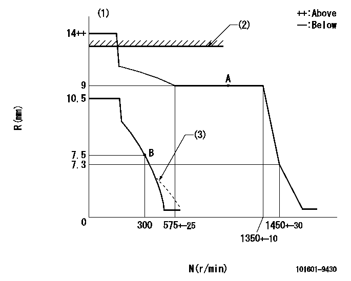
N:Pump speed
R:Rack position (mm)
(1)Target notch: K
(2)RACK LIMIT: RAL
(3)Damper spring setting: DL
----------
K=20 RAL=12+0.2mm DL=7-0.2mm
----------
----------
K=20 RAL=12+0.2mm DL=7-0.2mm
----------
Speed control lever angle

F:Full speed
I:Idle
(1)Stopper bolt setting
----------
----------
a=24deg+-5deg b=26deg+-5deg
----------
----------
a=24deg+-5deg b=26deg+-5deg
Stop lever angle

N:Pump normal
S:Stop the pump.
----------
----------
a=10.5deg+-5deg b=53deg+-5deg
----------
----------
a=10.5deg+-5deg b=53deg+-5deg
0000001501 GOV FULL LOAD ADJUSTMENT
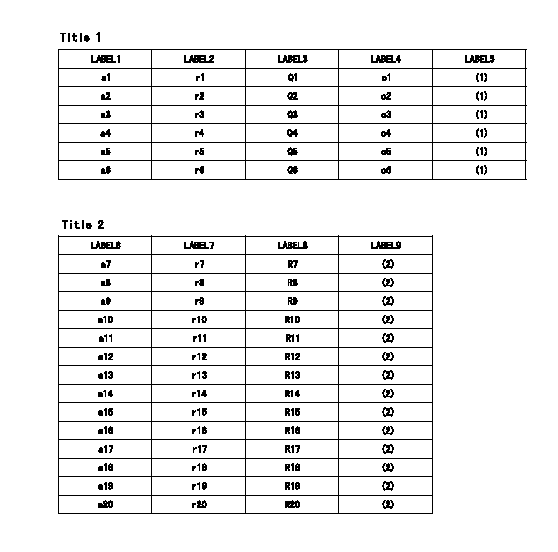
Title1:Full load stopper adjustment
Title2:Governor set speed
LABEL1:Distinguishing
LABEL2:Pump speed (r/min)
LABEL3:Ave. injection quantity (mm3/st)
LABEL4:Max. var. bet. cyl.
LABEL5:Remarks
LABEL6:Distinguishing
LABEL7:Governor set speed (r/min)
LABEL8:Maximum no-load speed (r/min)
LABEL9:Remarks
(1)Adjustment conditions are the same as those for measuring injection quantity.
(2)At high idle rack position L
----------
L=7.3mm
----------
a1=A a2=B a3=- a4=- a5=- a6=- r1=900r/min r2=900r/min r3=- r4=- r5=- r6=- Q1=54.7+-1.6mm3/st Q2=51.4+-1.6mm3/st Q3=- Q4=- Q5=- Q6=- c1=+-2% c2=+-2% c3=- c4=- c5=- c6=- a7=27 a8=26 a9=25 a10=24 a11=23 a12=22 a13=21 a14=20 a15=19 a16=18 a17=17 a18=16 a19=15 a20=14 r7=1350r/min r8=1300r/min r9=1250r/min r10=1200r/min r11=1150r/min r12=1100r/min r13=1050r/min r14=1000r/min r15=950r/min r16=900r/min r17=850r/min r18=800r/min r19=750r/min r20=700r/min R7=1450+-33r/min R8=1395+-32r/min R9=1340+-31r/min R10=1290+-30r/min R11=1235+-28r/min R12=1180+-27r/min R13=1130+-26r/min R14=1075+-25r/min R15=1020+-23r/min R16=965+-22r/min R17=915+-22r/min R18=860+-20r/min R19=805+-18r/min R20=750+-17r/min
----------
L=7.3mm
----------
a1=A a2=B a3=- a4=- a5=- a6=- r1=900r/min r2=900r/min r3=- r4=- r5=- r6=- Q1=54.7+-1.6mm3/st Q2=51.4+-1.6mm3/st Q3=- Q4=- Q5=- Q6=- c1=+-2% c2=+-2% c3=- c4=- c5=- c6=- a7=27 a8=26 a9=25 a10=24 a11=23 a12=22 a13=21 a14=20 a15=19 a16=18 a17=17 a18=16 a19=15 a20=14 r7=1350r/min r8=1300r/min r9=1250r/min r10=1200r/min r11=1150r/min r12=1100r/min r13=1050r/min r14=1000r/min r15=950r/min r16=900r/min r17=850r/min r18=800r/min r19=750r/min r20=700r/min R7=1450+-33r/min R8=1395+-32r/min R9=1340+-31r/min R10=1290+-30r/min R11=1235+-28r/min R12=1180+-27r/min R13=1130+-26r/min R14=1075+-25r/min R15=1020+-23r/min R16=965+-22r/min R17=915+-22r/min R18=860+-20r/min R19=805+-18r/min R20=750+-17r/min
Timing setting

(1)Pump vertical direction
(2)Coupling's key groove position at No 1 cylinder's beginning of injection
(3)-
(4)-
----------
----------
a=(30deg)
----------
----------
a=(30deg)
Information:
Introduction
The problem that is identified below does not have a known permanent solution. Until a known permanent solution is known, use the solution that is identified below.Problem
Multiple dealers have found that the "ARD Nozzle Heater Circuit Test" in Cat ET does not work after flashing to PROD 5 engine software. An error message is returned that says calibration unsuccessful when the start button is pressed. Refer to the Illustration below.
Illustration 1 g02839458
Illustration 2 g02839481
Solution
The "ARD Nozzle Heater Circuit Test" is still functional despite the error being shown. An engine software solution for this issue is in process and should be released soon.The test should be working while the calibration error is present as long as the appropriate conditions are met to run the test. Once finished troubleshooting, the technician should select "Finish" to end the circuit test.