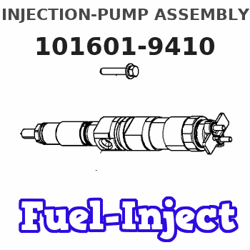
Information injection-pump assembly
ZEXEL
101601-9410
1016019410
Rating:
Cross reference number
ZEXEL
101601-9410
1016019410
Zexel num
Bosch num
Firm num
Name
Calibration Data:
Adjustment conditions
Test oil
1404 Test oil ISO4113 or {SAEJ967d}
1404 Test oil ISO4113 or {SAEJ967d}
Test oil temperature
degC
40
40
45
Nozzle and nozzle holder
105780-8140
Bosch type code
EF8511/9A
Nozzle
105780-0000
Bosch type code
DN12SD12T
Nozzle holder
105780-2080
Bosch type code
EF8511/9
Opening pressure
MPa
17.2
Opening pressure
kgf/cm2
175
Injection pipe
Outer diameter - inner diameter - length (mm) mm 6-2-600
Outer diameter - inner diameter - length (mm) mm 6-2-600
Overflow valve opening pressure
kPa
157
123
191
Overflow valve opening pressure
kgf/cm2
1.6
1.25
1.95
Tester oil delivery pressure
kPa
157
157
157
Tester oil delivery pressure
kgf/cm2
1.6
1.6
1.6
Direction of rotation (viewed from drive side)
Right R
Right R
Injection timing adjustment
Direction of rotation (viewed from drive side)
Right R
Right R
Injection order
1-4-2-6-
3-5
Pre-stroke
mm
3
2.95
3.05
Beginning of injection position
Drive side NO.1
Drive side NO.1
Difference between angles 1
Cal 1-4 deg. 60 59.5 60.5
Cal 1-4 deg. 60 59.5 60.5
Difference between angles 2
Cyl.1-2 deg. 120 119.5 120.5
Cyl.1-2 deg. 120 119.5 120.5
Difference between angles 3
Cal 1-6 deg. 180 179.5 180.5
Cal 1-6 deg. 180 179.5 180.5
Difference between angles 4
Cal 1-3 deg. 240 239.5 240.5
Cal 1-3 deg. 240 239.5 240.5
Difference between angles 5
Cal 1-5 deg. 300 299.5 300.5
Cal 1-5 deg. 300 299.5 300.5
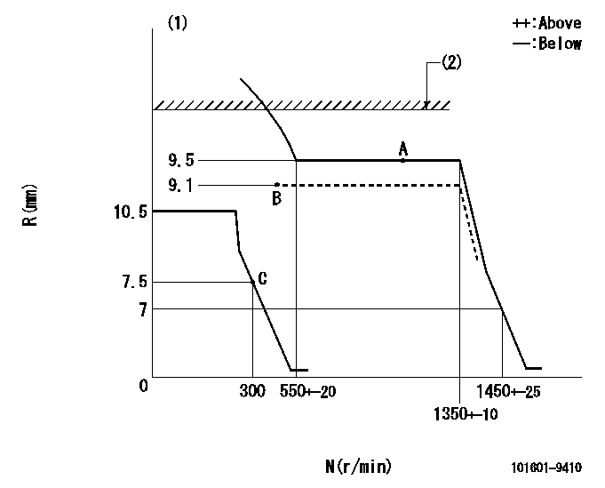
Injection quantity adjustment
Adjusting point
A
Rack position
9.5
Pump speed
r/min
750
750
750
Average injection quantity
mm3/st.
63
61.4
64.6
Max. variation between cylinders
%
0
-3.5
3.5
Basic
*
Fixing the lever
*
Boost pressure
kPa
50
50
Boost pressure
mmHg
375
375
Injection quantity adjustment_02
Adjusting point
B
Rack position
9.1
Pump speed
r/min
500
500
500
Average injection quantity
mm3/st.
44.2
42.6
45.8
Max. variation between cylinders
%
0
-5
5
Fixing the lever
*
Boost pressure
kPa
0
0
0
Boost pressure
mmHg
0
0
0
Injection quantity adjustment_03
Adjusting point
C
Rack position
7.8+-0.5
Pump speed
r/min
300
300
300
Average injection quantity
mm3/st.
9.5
7.7
11.3
Max. variation between cylinders
%
0
-10
10
Fixing the rack
*
Boost pressure
kPa
0
0
0
Boost pressure
mmHg
0
0
0
Remarks
Adjust only variation between cylinders; adjust governor according to governor specifications.
Adjust only variation between cylinders; adjust governor according to governor specifications.
Boost compensator adjustment
Pump speed
r/min
600
600
600
Rack position
9.1
Boost pressure
kPa
16
14.7
17.3
Boost pressure
mmHg
120
110
130
Boost compensator adjustment_02
Pump speed
r/min
600
600
600
Rack position
9.5
Boost pressure
kPa
36.7
30
43.4
Boost pressure
mmHg
275
225
325
Timer adjustment
Pump speed
r/min
300
Advance angle
deg.
1
0.5
1.5
Timer adjustment_02
Pump speed
r/min
600-150
Advance angle
deg.
0
0
0
Timer adjustment_03
Pump speed
r/min
1250+-50
Advance angle
deg.
0
0
0
Remarks
Beginning of advance.
Beginning of advance.
Timer adjustment_04
Pump speed
r/min
1350
Advance angle
deg.
1
0.5
1.5
Timer adjustment_05
Pump speed
r/min
-
Advance angle
deg.
2.5
2.5
2.5
Remarks
Measure the actual speed, stop
Measure the actual speed, stop
Test data Ex:
Governor adjustment
N:Pump speed
R:Rack position (mm)
(1)Target notch: K
(2)Rack limit using excess fuel lever: L1
----------
K=12 L1=10+0.2mm
----------
----------
K=12 L1=10+0.2mm
----------
Speed control lever angle
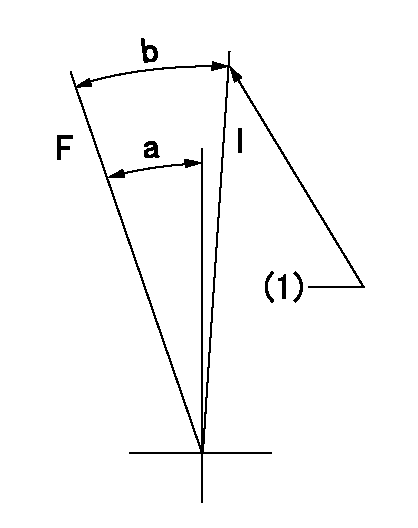
F:Full speed
I:Idle
(1)Stopper bolt setting
----------
----------
a=19deg+-3deg b=26deg+-5deg
----------
----------
a=19deg+-3deg b=26deg+-5deg
Stop lever angle
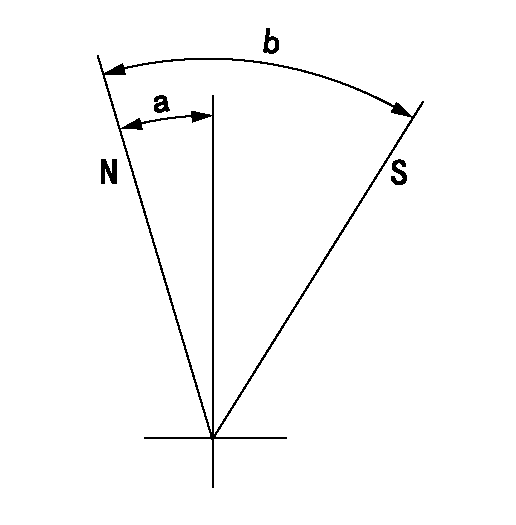
N:Pump normal
S:Stop the pump.
----------
----------
a=10.5deg+-5deg b=53deg+-5deg
----------
----------
a=10.5deg+-5deg b=53deg+-5deg
0000001501 GOV FULL LOAD ADJUSTMENT
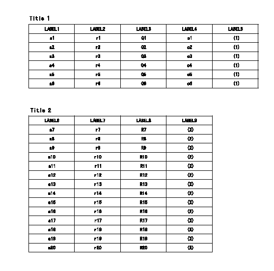
Title1:Full load stopper adjustment
Title2:Governor set speed
LABEL1:Distinguishing
LABEL2:Pump speed (r/min)
LABEL3:Ave. injection quantity (mm3/st)
LABEL4:Max. var. bet. cyl.
LABEL5:Remarks
LABEL6:Distinguishing
LABEL7:Governor set speed (r/min)
LABEL8:Maximum no-load speed (r/min)
LABEL9:Remarks
(1)Adjustment conditions are the same as those for measuring injection quantity.
(2)At high idle rack position L
----------
L=7mm
----------
a1=A a2=B a3=- a4=- a5=- a6=- r1=900r/min r2=750r/min r3=- r4=- r5=- r6=- Q1=73.2+-1.6mm3/st Q2=63+-1.6mm3/st Q3=- Q4=- Q5=- Q6=- c1=+-3.5% c2=+-3.5% c3=- c4=- c5=- c6=- a7=27 a8=26 a9=25 a10=24 a11=23 a12=22 a13=21 a14=20 a15=19 a16=18 a17=17 a18=16 a19=15 a20=- r7=1350r/min r8=1300r/min r9=1250r/min r10=1200r/min r11=1150r/min r12=1100r/min r13=1050r/min r14=1000r/min r15=950r/min r16=900r/min r17=850r/min r18=800r/min r19=750r/min r20=- R7=1450+-33r/min R8=1395+-32r/min R9=1340+-31r/min R10=1290+-30r/min R11=1235+-28r/min R12=1180+-27r/min R13=1130+-26r/min R14=1075+-25r/min R15=1020+-23r/min R16=965+-22r/min R17=915+-22r/min R18=860+-20r/min R19=805+-18r/min R20=-
----------
L=7mm
----------
a1=A a2=B a3=- a4=- a5=- a6=- r1=900r/min r2=750r/min r3=- r4=- r5=- r6=- Q1=73.2+-1.6mm3/st Q2=63+-1.6mm3/st Q3=- Q4=- Q5=- Q6=- c1=+-3.5% c2=+-3.5% c3=- c4=- c5=- c6=- a7=27 a8=26 a9=25 a10=24 a11=23 a12=22 a13=21 a14=20 a15=19 a16=18 a17=17 a18=16 a19=15 a20=- r7=1350r/min r8=1300r/min r9=1250r/min r10=1200r/min r11=1150r/min r12=1100r/min r13=1050r/min r14=1000r/min r15=950r/min r16=900r/min r17=850r/min r18=800r/min r19=750r/min r20=- R7=1450+-33r/min R8=1395+-32r/min R9=1340+-31r/min R10=1290+-30r/min R11=1235+-28r/min R12=1180+-27r/min R13=1130+-26r/min R14=1075+-25r/min R15=1020+-23r/min R16=965+-22r/min R17=915+-22r/min R18=860+-20r/min R19=805+-18r/min R20=-
Timing setting

(1)Pump vertical direction
(2)Coupling's key groove position at No 1 cylinder's beginning of injection
(3)-
(4)-
----------
----------
a=(30deg)
----------
----------
a=(30deg)
Information:
(1) Thickness of spacer plate ... 9.970 0.025 mm (.3925 .0010 in) Thickness of spacer plate gasket ... 0.208 0.025 mm (.0082 .0010 in) For height of liner over top of spacer plate make reference to Cylinder Liner Projection.(2) Camshaft bearing bore (installed) ... 58.80 0.06 mm (2.315 .002 in) Bore in block for camshaft bearings ... 65.100 0.025 mm (2.5630 .0010 in)(3) Bore in block for main bearings (standard size) ... 96.926 0.013 mm (3.8160 .0005 in) Bore in block for main bearings 0.51 mm (.020 in) oversize ... 97.436 0.013 mm (3.8361 .0005 in)(4) Dimension from center of main bearing bore to top of cylinder block (new) ... 383.515 0.165 mm (15.0990 .0064 in)(5) Dimension from center of main bearing bore to bottom of cylinder block (new) ... 153.99 0.10 mm (6.063 .004 in)(6) Tighten bolts holding bearing caps for main bearings to a torque of: a. Put 6V4876 Molycoat Lubricant on threads and washer face.b. Tighten all bolts to a torque of ... 41 4 N m (30 3 lb ft)c. Put a mark on each bolt and cap.d. Tighten all bolts from mark ... 90 5 degrees Install bearing caps with the part number toward the front of the engine. Be sure that the mark (number) on the bearing cap next to the bolt hole is in agreement with the mark in the cylinder block.(7) Clearance between main bearing cap and cylinder block ... 0.033 mm (.0013 in) tight to ... 0.043 mm (.0017 in) loose Main bearing cap width ... 165.095 0.020 mm (6.4998 .0008 in)Width of cylinder block for main bearing cap ... 165.100 0.018 mm (6.5000 .0007 in) (8) Piston cooling orifice.
There are holes in the bores for the main bearings, between the cylinders for piston cooling orifices. These holes must have orifices (8) installed.
(9) Distance two dowels extend from the surface of the cylinder block ... 19.8 0.5 mm (.78 .02 in)(10) Distance hollow dowel extends from the surface of the cylinder block ... 16.0 0.5 mm (.63 .02 in)(11) Depth to install two dowels below the surface of the cylinder block (apply 7M7456 Bearing Mount) ... 1.0 0.5 mm (.04 .02 in)(12) Distance dowels extend from the front face of the cylinder block ... 22.4 0.5 mm (.88 .02 in)(13) Distance stud extends from the front face of the cylinder block ... 15.7 0.5 mm (.62 .02 in)(14) Distance two dowels extend from the rear face of the cylinder block ... 12.7 0.5 mm (.50 .02 in) Check piston cooling jets by passing a .090 mm (.0035 in) diameter drill rod thru jet and a .050 mm (.0020 in) circle located at J. Dimensions