Information injection-pump assembly
ZEXEL
101601-9020
1016019020
NISSAN-DIESEL
16700Z5502
16700z5502

Rating:
Service parts 101601-9020 INJECTION-PUMP ASSEMBLY:
1.
_
6.
COUPLING PLATE
7.
COUPLING PLATE
8.
_
9.
_
11.
Nozzle and Holder
16600-Z5502
12.
Open Pre:MPa(Kqf/cm2)
19.6{200}
15.
NOZZLE SET
Cross reference number
ZEXEL
101601-9020
1016019020
NISSAN-DIESEL
16700Z5502
16700z5502
Zexel num
Bosch num
Firm num
Name
101601-9020
16700Z5502 NISSAN-DIESEL
INJECTION-PUMP ASSEMBLY
FD6 * K
FD6 * K
Calibration Data:
Adjustment conditions
Test oil
1404 Test oil ISO4113 or {SAEJ967d}
1404 Test oil ISO4113 or {SAEJ967d}
Test oil temperature
degC
40
40
45
Nozzle and nozzle holder
105780-8140
Bosch type code
EF8511/9A
Nozzle
105780-0000
Bosch type code
DN12SD12T
Nozzle holder
105780-2080
Bosch type code
EF8511/9
Opening pressure
MPa
17.2
Opening pressure
kgf/cm2
175
Injection pipe
Outer diameter - inner diameter - length (mm) mm 6-2-600
Outer diameter - inner diameter - length (mm) mm 6-2-600
Overflow valve
132424-0620
Overflow valve opening pressure
kPa
157
123
191
Overflow valve opening pressure
kgf/cm2
1.6
1.25
1.95
Tester oil delivery pressure
kPa
157
157
157
Tester oil delivery pressure
kgf/cm2
1.6
1.6
1.6
Direction of rotation (viewed from drive side)
Right R
Right R
Injection timing adjustment
Direction of rotation (viewed from drive side)
Right R
Right R
Injection order
1-4-2-6-
3-5
Pre-stroke
mm
2.4
2.35
2.45
Rack position
Point A R=A
Point A R=A
Beginning of injection position
Drive side NO.1
Drive side NO.1
Difference between angles 1
Cal 1-4 deg. 60 59.5 60.5
Cal 1-4 deg. 60 59.5 60.5
Difference between angles 2
Cyl.1-2 deg. 120 119.5 120.5
Cyl.1-2 deg. 120 119.5 120.5
Difference between angles 3
Cal 1-6 deg. 180 179.5 180.5
Cal 1-6 deg. 180 179.5 180.5
Difference between angles 4
Cal 1-3 deg. 240 239.5 240.5
Cal 1-3 deg. 240 239.5 240.5
Difference between angles 5
Cal 1-5 deg. 300 299.5 300.5
Cal 1-5 deg. 300 299.5 300.5
Injection quantity adjustment
Adjusting point
A
Rack position
10.3
Pump speed
r/min
1600
1600
1600
Average injection quantity
mm3/st.
60
57.7
62.3
Max. variation between cylinders
%
0
-3
3
Fixing the lever
*
Injection quantity adjustment_02
Adjusting point
B
Rack position
10.3
Pump speed
r/min
1000
1000
1000
Average injection quantity
mm3/st.
55.7
54.1
57.3
Max. variation between cylinders
%
0
-2
2
Basic
*
Fixing the lever
*
Injection quantity adjustment_03
Adjusting point
C
Rack position
10.3
Pump speed
r/min
700
700
700
Average injection quantity
mm3/st.
44.5
42.9
46.1
Max. variation between cylinders
%
0
-4
4
Fixing the lever
*
Injection quantity adjustment_04
Adjusting point
D
Rack position
8.9+-0.5
Pump speed
r/min
300
300
300
Average injection quantity
mm3/st.
8
6.8
9.2
Max. variation between cylinders
%
0
-15
15
Fixing the rack
*
Timer adjustment
Pump speed
r/min
450+100-
50
Advance angle
deg.
0
0
0
Remarks
Start
Start
Timer adjustment_02
Pump speed
r/min
800
Advance angle
deg.
1.5
1
2
Timer adjustment_03
Pump speed
r/min
1100
Advance angle
deg.
3.5
3
4
Timer adjustment_04
Pump speed
r/min
1450
Advance angle
deg.
6
5.5
6.5
Remarks
Finish
Finish
Test data Ex:
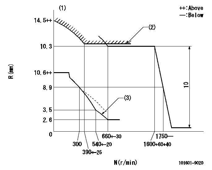
Governor adjustment

N:Pump speed
R:Rack position (mm)
(1)Beginning of damper spring operation: DL
(2)Excess fuel setting for starting: SXL
(3)Torque control spring setting
----------
DL=8.5-0.2mm SXL=11.6+0.2mm
----------
----------
DL=8.5-0.2mm SXL=11.6+0.2mm
----------
0000000901

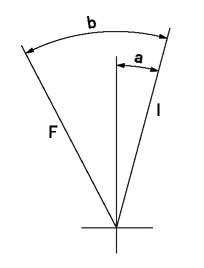
F:Full load
I:Idle
----------
----------
a=6deg+-5deg b=27.5deg+-3deg
----------
----------
a=6deg+-5deg b=27.5deg+-3deg
Information:
A "single" winding (single output) magnetic pickup sensor is recommended for use as a vehicle speed sensor for the 3406B (PEEC III) System. Experience has shown that use of a "dual" winding (dual output) vehicle speed sensor can contribute to electrical noise problems. Vehicle speed buffer negative battery pin must be connected to engine ground, not to cab ground. The vehicle speed circuit consists of the Vehicle Speed Sensor, the Vehicle Speed Buffer and associated wiring. The sensor is a standard magnetic pickup and is supplied by the truck manufacturer. It senses the movement of teeth on the output shaft of the transmission. The buffer (Caterpillar supplied) takes the signal from the sensor, conditions it and sends it to both the ECM and the vehicle speedometer.There are three acceptable options for wiring of the vehicle speed circuit: For all three options, the Vehicle Speed Buffer should be grounded to the same ground point as the ECM. On 3406B (PEEC III) Engines, the ECM ground point is the cylinder head ground stud.Option 1. Use separate sensors for the Vehicle Speed Buffer and the speedometer, with the second sensor supplying the signal to the speedometer. This option completely isolates the two circuits and is preferred by Caterpillar. See Illustration 1.
Illustration 1
Recommended vehicle speed circuit wiring when using two separate sensors.Option 2. Use a single sensor, with the Vehicle Speed Buffer supplying the signal to the speedometer. This option provides good results when correctly wired. Note that this illustration is electrically identical to the schematic in the 3406B (PEEC III) Diesel Truck Engine Electrical Schematic, Form No SENR5152, which is in the complete Service Manual, 3406B (PEEC III) Diesel Truck Engine, Form No. SENR5150, but shows the required grounding for the speedometer more clearly.The 3E0020 buffer provides a second output line for speedometer requiring two signal lines.
Illustration 2
Recommended vehicle speed circuit wiring using a single sensor.Option 3. Use a dual winding sensor, with the second winding supplying the signal to the speedometer. This option is not preferred by Caterpillar, but can provide acceptable results if the sensor is installed correctly.Dual winding sensors may be used in some new OEM installations which have been specifically reviewed by Caterpillar.
Illustration 3
Recommended vehicle speed circuit wiring when using a dual-winding sensor.The Vehicle Speed Buffer has a five-pin connector (J14/P14) with pins to battery negative, battery positive, the ECM and two for the vehicle speedometer.+ Battery (Pin A) supplies battery power to the buffer.- Battery (Pin B) provides battery ground through the cylinder head ground stud.Buffer Output to the ECM (Pin D) supplies a series of 5 volt DC pulses to the ECM. The frequency of the pulses varies directly with the speed of the vehicle.When a single Vehicle Speed Sensor is used, as in Illustration 2, the vehicle speed signal to the speedometer is provided by the buffer.The 3E0020 buffer has two speedometer outputs, one at P14, Pin C and one at P14, Pin E. Output at each one is a series of -8 volt
Have questions with 101601-9020?
Group cross 101601-9020 ZEXEL
Nissan-Diesel
101601-9020
16700Z5502
INJECTION-PUMP ASSEMBLY
FD6
FD6