Information injection-pump assembly
ZEXEL
101601-8862
1016018862
ISUZU
1156017422
1156017422
Rating:
Service parts 101601-8862 INJECTION-PUMP ASSEMBLY:
1.
_
3.
GOVERNOR
7.
COUPLING PLATE
8.
_
9.
_
11.
Nozzle and Holder
1-15300-104-2
12.
Open Pre:MPa(Kqf/cm2)
18.1{185}

15.
NOZZLE SET
Cross reference number
ZEXEL
101601-8862
1016018862
ISUZU
1156017422
1156017422
Zexel num
Bosch num
Firm num
Name
Calibration Data:
Adjustment conditions
Test oil
1404 Test oil ISO4113 or {SAEJ967d}
1404 Test oil ISO4113 or {SAEJ967d}
Test oil temperature
degC
40
40
45
Nozzle and nozzle holder
105780-8140
Bosch type code
EF8511/9A
Nozzle
105780-0000
Bosch type code
DN12SD12T
Nozzle holder
105780-2080
Bosch type code
EF8511/9
Opening pressure
MPa
17.2
Opening pressure
kgf/cm2
175
Injection pipe
Outer diameter - inner diameter - length (mm) mm 6-2-600
Outer diameter - inner diameter - length (mm) mm 6-2-600
Overflow valve opening pressure
kPa
157
123
191
Overflow valve opening pressure
kgf/cm2
1.6
1.25
1.95
Tester oil delivery pressure
kPa
157
157
157
Tester oil delivery pressure
kgf/cm2
1.6
1.6
1.6
Direction of rotation (viewed from drive side)
Right R
Right R
Injection timing adjustment
Direction of rotation (viewed from drive side)
Right R
Right R
Injection order
1-5-3-6-
2-4
Pre-stroke
mm
3.6
3.55
3.65
Beginning of injection position
Drive side NO.1
Drive side NO.1
Difference between angles 1
Cal 1-5 deg. 60 59.5 60.5
Cal 1-5 deg. 60 59.5 60.5
Difference between angles 2
Cal 1-3 deg. 120 119.5 120.5
Cal 1-3 deg. 120 119.5 120.5
Difference between angles 3
Cal 1-6 deg. 180 179.5 180.5
Cal 1-6 deg. 180 179.5 180.5
Difference between angles 4
Cyl.1-2 deg. 240 239.5 240.5
Cyl.1-2 deg. 240 239.5 240.5
Difference between angles 5
Cal 1-4 deg. 300 299.5 300.5
Cal 1-4 deg. 300 299.5 300.5
Injection quantity adjustment
Adjusting point
-
Rack position
12.6
Pump speed
r/min
1000
1000
1000
Average injection quantity
mm3/st.
76.8
75.2
78.4
Max. variation between cylinders
%
0
-2.5
2.5
Basic
*
Fixing the rack
*
Standard for adjustment of the maximum variation between cylinders
*
Injection quantity adjustment_02
Adjusting point
H
Rack position
9.5+-0.5
Pump speed
r/min
260
260
260
Average injection quantity
mm3/st.
8.1
6.8
9.4
Max. variation between cylinders
%
0
-14
14
Fixing the rack
*
Standard for adjustment of the maximum variation between cylinders
*
Injection quantity adjustment_03
Adjusting point
A
Rack position
R1(12.6)
Pump speed
r/min
1000
1000
1000
Average injection quantity
mm3/st.
76.8
75.8
77.8
Basic
*
Fixing the lever
*
Injection quantity adjustment_04
Adjusting point
I
Rack position
15.3+-0.
5
Pump speed
r/min
150
150
150
Average injection quantity
mm3/st.
92
92
100
Fixing the lever
*
Rack limit
*
Timer adjustment
Pump speed
r/min
1350--
Advance angle
deg.
0
0
0
Remarks
Start
Start
Timer adjustment_02
Pump speed
r/min
1300
Advance angle
deg.
0.5
Timer adjustment_03
Pump speed
r/min
1400
Advance angle
deg.
2
1.5
2.5
Timer adjustment_04
Pump speed
r/min
1500
Advance angle
deg.
4.5
4
5
Remarks
Finish
Finish
Test data Ex:
Governor adjustment
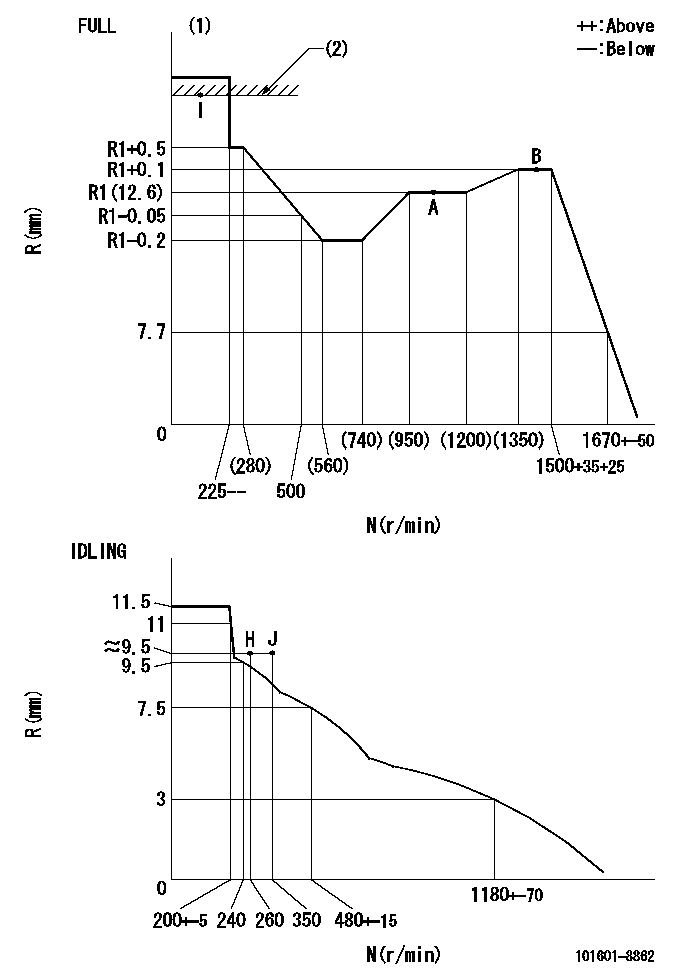
N:Pump speed
R:Rack position (mm)
(1)Torque cam stamping: T1
(2)RACK LIMIT
----------
T1=C32
----------
----------
T1=C32
----------
Speed control lever angle
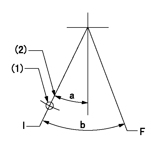
F:Full speed
I:Idle
(1)Use the hole at R = aa
(2)Stopper bolt set position 'H'
----------
aa=35mm
----------
a=42deg+-5deg b=(43deg)+-3deg
----------
aa=35mm
----------
a=42deg+-5deg b=(43deg)+-3deg
Stop lever angle

N:Pump normal
S:Stop the pump.
----------
----------
a=25deg+-5deg b=40deg+-5deg
----------
----------
a=25deg+-5deg b=40deg+-5deg
Timing setting

(1)Pump vertical direction
(2)Position of timer's threaded hole at No 1 cylinder's beginning of injection
(3)B.T.D.C.: aa
(4)-
----------
aa=13deg
----------
a=(60deg)
----------
aa=13deg
----------
a=(60deg)
Information:
1. Remove fuel line (1) from the fuel transfer pump.2. Put caps in the fuel line openings to prevent fuel system contamination.3. Remove bolts (2), and remove fuel transfer pump (3). Check the condition of the O-ring seal on the fuel transfer pump. If necessary, make a replacement. The following steps are for installation of the fuel transfer pump.4. Be sure the O-ring seal is in position on the fuel transfer pump. Put clean engine oil on the O-ring seal.5. Put fuel transfer pump (3) in position, and install the bolts that hold it in place.6. Remove the caps from the fuel line openings, and install fuel line (1).Disassemble Fuel Transfer Pump
Start By:a. remove fuel transfer pump 1. Remove seal (1) from the fuel transfer pump.
Cover (2) is under spring tension. Remove the bolts that hold cover (2) slowly to prevent injury.
2. Remove bolts (3) and cover (2) from the housing. 3. Remove seals (4) and valve (5) from cover (2). 4. Remove spring (6) from the piston.
Mark the orientation of valve (8) as to its location in the housing.
5. Remove washer (7), valve (8) and the seal from the housing. 6. Remove piston (9) and sleeve (10) from the housing. 7. Remove seal (11) from sleeve (12). 8. Remove guide and tappet assembly (13) from the housing. 9. Remove seal (14) from guide (15).
If tappet (17) or the guide are damaged or worn, they must be replaced as a unit.
10. Remove ring (16) from tappet (17) and the tappet from guide (15). 11. Remove the bolts and cover (18) from the housing. 12. Remove seal (19) from cover (18). 13. Remove valve (20) from the housing if necessary.Assemble Fuel Transfer Pump
1. Install valve (20) in housing as shown. 2. Put clean fuel on seal (19), and install it on cover (18).3. Install cover (18) on the housing.
The tappet and guide must be serviced as a unit.
4. Install tappet (17) in guide (15). Install ring (16) on tappet (17) to hold the tappet in the guide. 5. Put clean fuel on seal (14), and install it on guide and tappet assembly (13).6. Install guide and tappet assembly (13) in the housing as shown. 7. Put clean fuel on seal (11), and install it on sleeve (12).8. Install sleeve (12) in the housing. 9. Install piston (9) in the housing. 10. Install seal, valve (8) and washer (7) in the housing as shown. Be sure valve (8) is the correct position in the housing. 11. Install spring (6) in the piston. 12. Install valve (5) in cover (2) as shown.13. Put clean fuel on seals (4), and put them in position on cover (2).14. Install cover (2) on the housing. 15. Put seal (1) in position on the fuel transfer pump.16. Install the fuel transfer pump on the fuel injection pump housing.End By:a. install fuel transfer pump