Information injection-pump assembly
BOSCH
9 400 610 020
9400610020
ZEXEL
101601-8671
1016018671
ISUZU
1156016813
1156016813
Rating:
Service parts 101601-8671 INJECTION-PUMP ASSEMBLY:
1.
_
7.
COUPLING PLATE
8.
_
9.
_
11.
Nozzle and Holder
1-15300-105-2
12.
Open Pre:MPa(Kqf/cm2)
18.1{185}

15.
NOZZLE SET
Cross reference number
BOSCH
9 400 610 020
9400610020
ZEXEL
101601-8671
1016018671
ISUZU
1156016813
1156016813
Zexel num
Bosch num
Firm num
Name
101601-8671
9 400 610 020
1156016813 ISUZU
INJECTION-PUMP ASSEMBLY
6BD1-T * K
6BD1-T * K
Calibration Data:
Adjustment conditions
Test oil
1404 Test oil ISO4113 or {SAEJ967d}
1404 Test oil ISO4113 or {SAEJ967d}
Test oil temperature
degC
40
40
45
Nozzle and nozzle holder
105780-8140
Bosch type code
EF8511/9A
Nozzle
105780-0000
Bosch type code
DN12SD12T
Nozzle holder
105780-2080
Bosch type code
EF8511/9
Opening pressure
MPa
17.2
Opening pressure
kgf/cm2
175
Injection pipe
Outer diameter - inner diameter - length (mm) mm 6-2-600
Outer diameter - inner diameter - length (mm) mm 6-2-600
Overflow valve opening pressure
kPa
157
123
191
Overflow valve opening pressure
kgf/cm2
1.6
1.25
1.95
Tester oil delivery pressure
kPa
157
157
157
Tester oil delivery pressure
kgf/cm2
1.6
1.6
1.6
Direction of rotation (viewed from drive side)
Right R
Right R
Injection timing adjustment
Direction of rotation (viewed from drive side)
Right R
Right R
Injection order
1-5-3-6-
2-4
Pre-stroke
mm
3.4
3.35
3.45
Beginning of injection position
Drive side NO.1
Drive side NO.1
Difference between angles 1
Cal 1-5 deg. 60 59.5 60.5
Cal 1-5 deg. 60 59.5 60.5
Difference between angles 2
Cal 1-3 deg. 120 119.5 120.5
Cal 1-3 deg. 120 119.5 120.5
Difference between angles 3
Cal 1-6 deg. 180 179.5 180.5
Cal 1-6 deg. 180 179.5 180.5
Difference between angles 4
Cyl.1-2 deg. 240 239.5 240.5
Cyl.1-2 deg. 240 239.5 240.5
Difference between angles 5
Cal 1-4 deg. 300 299.5 300.5
Cal 1-4 deg. 300 299.5 300.5
Injection quantity adjustment
Adjusting point
-
Rack position
10.6
Pump speed
r/min
1000
1000
1000
Average injection quantity
mm3/st.
72
70.4
73.6
Max. variation between cylinders
%
0
-2.5
2.5
Basic
*
Fixing the rack
*
Standard for adjustment of the maximum variation between cylinders
*
Injection quantity adjustment_02
Adjusting point
-
Rack position
9.6+-0.5
Pump speed
r/min
290
290
290
Average injection quantity
mm3/st.
9.4
8.1
10.7
Max. variation between cylinders
%
0
-14
14
Fixing the rack
*
Standard for adjustment of the maximum variation between cylinders
*
Remarks
Adjust only variation between cylinders; adjust governor according to governor specifications.
Adjust only variation between cylinders; adjust governor according to governor specifications.
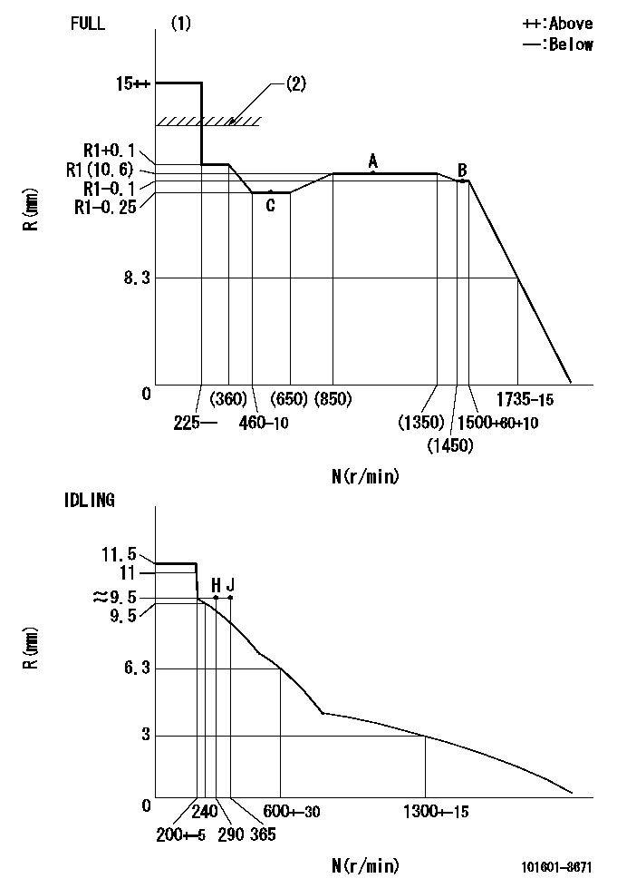
Injection quantity adjustment_03
Adjusting point
A
Rack position
R1(10.6)
Pump speed
r/min
1000
1000
1000
Average injection quantity
mm3/st.
72
71
73
Basic
*
Fixing the lever
*
Injection quantity adjustment_04
Adjusting point
B
Rack position
R1-0.1
Pump speed
r/min
1500
1500
1500
Average injection quantity
mm3/st.
76.5
73.3
79.7
Fixing the lever
*
Injection quantity adjustment_05
Adjusting point
C
Rack position
R1-0.25
Pump speed
r/min
500
500
500
Average injection quantity
mm3/st.
46.5
43.3
49.7
Fixing the lever
*
Timer adjustment
Pump speed
r/min
1050--
Advance angle
deg.
0
0
0
Remarks
Start
Start
Timer adjustment_02
Pump speed
r/min
1000
Advance angle
deg.
0.5
Timer adjustment_03
Pump speed
r/min
(1300)
Advance angle
deg.
1
0.5
1.5
Remarks
Finish
Finish
Test data Ex:
Governor adjustment
N:Pump speed
R:Rack position (mm)
(1)Torque cam stamping: T1
(2)RACK LIMIT: RAL
----------
T1=B51 RAL=13.5+0.2mm
----------
----------
T1=B51 RAL=13.5+0.2mm
----------
Speed control lever angle

F:Full speed
I:Idle
(1)Use the hole at R = aa
(2)Stopper bolt setting
----------
aa=35mm
----------
a=40deg+-5deg b=32deg+-3deg
----------
aa=35mm
----------
a=40deg+-5deg b=32deg+-3deg
Stop lever angle

N:Pump normal
S:Stop the pump.
----------
----------
a=25deg+-5deg b=40deg+-5deg
----------
----------
a=25deg+-5deg b=40deg+-5deg
0000001501 TAMPER PROOF
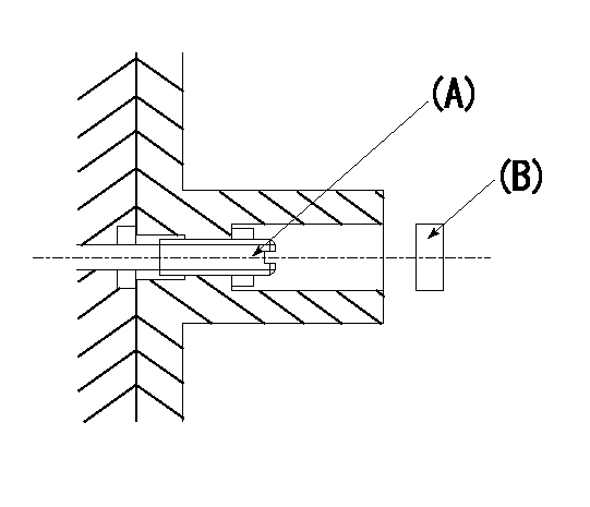
Tamper proof adjustment
(1)Set the full load screw at rack position Ra+0.4.
(2)Set the full load position Ra using screw (A).
----------
Ra=R1(10.6)mm
----------
----------
Ra=R1(10.6)mm
----------
Timing setting

(1)Pump vertical direction
(2)Position of timer's threaded hole at No 1 cylinder's beginning of injection
(3)B.T.D.C.: aa
(4)-
----------
aa=16deg
----------
a=(60deg)
----------
aa=16deg
----------
a=(60deg)
Information:
1. Disconnect water supply hose from water pump inlet.2. Remove connector pipe (1), remove two bolts (2) and remove oil fill pipe (3). 3. Remove bolts (4) and (5) then remove the water pump. The following steps are for the installation of the water pump.4. Position the water pump and install two bolts (4) and (5). Tighten the two bolts evenly.5. Position connector pipe (1) and gaskets then install the bolts.6. Install oil fill pipe (3). Be sure the gasket is in position between the regulator and pipe and install bolts (2).End By:a. Install alternatorb. Fill the cooling system to the specified level. See the Maintenance ManualDisassemble & Assemble Water Pump
Start By:a. remove water pump 1. Remove three bolts (1) and remove cover (2). 2. Use an M12 X 1.75 bolt to force impeller (3) from shaft (4). Install forcing bolt in impeller as indicated by arrow. Hold impeller and screw bolt in until impeller comes off shaft. 3. Remove bolt (5), washer (6), bearing (7) and gear (8). 4. Remove three bolts (9) and remove cover (10) with bearing (11). 5. Press shaft (4) out of seal (12).
Do not allow shaft (4) to fall to the floor, damage may occur to the shaft.
6. Remove seal (12) and seal (13) from water pump housing. The following steps are for the assembly of the water pump. 7. Using driver group, install seal (13). Refer to illustration to see direction of seal lip. Lubricate shaft seal area with engine oil.8. Assemble shaft (4), bearing (11) and cover (10). Position assembly into seal and housing then install bolts (9). 9. Position the housing and shaft assembly in a press. Position seal (12) on shaft (4). 10. Position tool (A) and press seal into place. 11. Position the water pump in a press, position impeller (3) and press it into place. Dimension X is 1.5 0.5 mm (.059 .020 in).12. Position seal and cover (2), then install bolts (1).End By:a. install water pump
Have questions with 101601-8671?
Group cross 101601-8671 ZEXEL
Isuzu
101601-8671
9 400 610 020
1156016813
INJECTION-PUMP ASSEMBLY
6BD1-T
6BD1-T