Information injection-pump assembly
BOSCH
9 400 610 019
9400610019
ZEXEL
101601-8651
1016018651
ISUZU
1156016793
1156016793
Rating:
Include in #1:
106685-4375
as _
Cross reference number
BOSCH
9 400 610 019
9400610019
ZEXEL
101601-8651
1016018651
ISUZU
1156016793
1156016793
Zexel num
Bosch num
Firm num
Name
Calibration Data:
Adjustment conditions
Test oil
1404 Test oil ISO4113 or {SAEJ967d}
1404 Test oil ISO4113 or {SAEJ967d}
Test oil temperature
degC
40
40
45
Nozzle and nozzle holder
105780-8140
Bosch type code
EF8511/9A
Nozzle
105780-0000
Bosch type code
DN12SD12T
Nozzle holder
105780-2080
Bosch type code
EF8511/9
Opening pressure
MPa
17.2
Opening pressure
kgf/cm2
175
Injection pipe
Outer diameter - inner diameter - length (mm) mm 6-2-600
Outer diameter - inner diameter - length (mm) mm 6-2-600
Overflow valve opening pressure
kPa
157
123
191
Overflow valve opening pressure
kgf/cm2
1.6
1.25
1.95
Tester oil delivery pressure
kPa
157
157
157
Tester oil delivery pressure
kgf/cm2
1.6
1.6
1.6
Direction of rotation (viewed from drive side)
Right R
Right R
Injection timing adjustment
Direction of rotation (viewed from drive side)
Right R
Right R
Injection order
1-5-3-6-
2-4
Pre-stroke
mm
3.4
3.35
3.45
Beginning of injection position
Drive side NO.1
Drive side NO.1
Difference between angles 1
Cal 1-5 deg. 60 59.5 60.5
Cal 1-5 deg. 60 59.5 60.5
Difference between angles 2
Cal 1-3 deg. 120 119.5 120.5
Cal 1-3 deg. 120 119.5 120.5
Difference between angles 3
Cal 1-6 deg. 180 179.5 180.5
Cal 1-6 deg. 180 179.5 180.5
Difference between angles 4
Cyl.1-2 deg. 240 239.5 240.5
Cyl.1-2 deg. 240 239.5 240.5
Difference between angles 5
Cal 1-4 deg. 300 299.5 300.5
Cal 1-4 deg. 300 299.5 300.5
Injection quantity adjustment
Adjusting point
-
Rack position
10.6
Pump speed
r/min
1000
1000
1000
Average injection quantity
mm3/st.
72
70.4
73.6
Max. variation between cylinders
%
0
-2.5
2.5
Basic
*
Fixing the rack
*
Standard for adjustment of the maximum variation between cylinders
*
Injection quantity adjustment_02
Adjusting point
-
Rack position
9.6+-0.5
Pump speed
r/min
290
290
290
Average injection quantity
mm3/st.
9.4
8.1
10.7
Max. variation between cylinders
%
0
-14
14
Fixing the rack
*
Standard for adjustment of the maximum variation between cylinders
*
Remarks
Adjust only variation between cylinders; adjust governor according to governor specifications.
Adjust only variation between cylinders; adjust governor according to governor specifications.
Injection quantity adjustment_03
Adjusting point
A
Rack position
R1(10.6)
Pump speed
r/min
1000
1000
1000
Average injection quantity
mm3/st.
72
71
73
Basic
*
Fixing the lever
*
Injection quantity adjustment_04
Adjusting point
B
Rack position
R1-0.1
Pump speed
r/min
1500
1500
1500
Average injection quantity
mm3/st.
76.5
73.3
79.7
Fixing the lever
*
Injection quantity adjustment_05
Adjusting point
C
Rack position
R1-0.25
Pump speed
r/min
500
500
500
Average injection quantity
mm3/st.
46.5
43.3
49.7
Fixing the lever
*
Timer adjustment
Pump speed
r/min
1050--
Advance angle
deg.
0
0
0
Remarks
Start
Start
Timer adjustment_02
Pump speed
r/min
1000
Advance angle
deg.
0.5
Timer adjustment_03
Pump speed
r/min
(1300)
Advance angle
deg.
1
0.5
1.5
Remarks
Finish
Finish
Test data Ex:
Governor adjustment
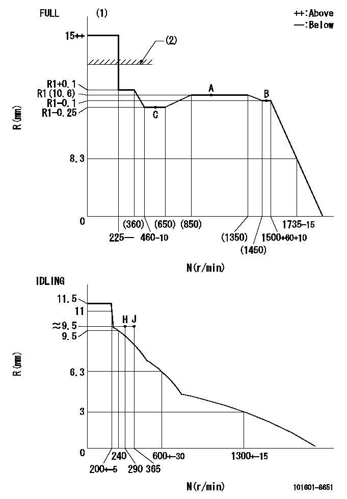
N:Pump speed
R:Rack position (mm)
(1)Torque cam stamping: T1
(2)RACK LIMIT: RAL
----------
T1=B51 RAL=13.5+0.2mm
----------
----------
T1=B51 RAL=13.5+0.2mm
----------
Speed control lever angle

F:Full speed
I:Idle
(1)Use the hole at R = aa
(2)Stopper bolt setting
----------
aa=35mm
----------
a=40deg+-5deg b=32deg+-3deg
----------
aa=35mm
----------
a=40deg+-5deg b=32deg+-3deg
Stop lever angle

N:Pump normal
S:Stop the pump.
----------
----------
a=25deg+-5deg b=40deg+-5deg
----------
----------
a=25deg+-5deg b=40deg+-5deg
Timing setting

(1)Pump vertical direction
(2)Position of timer's threaded hole at No 1 cylinder's beginning of injection
(3)B.T.D.C.: aa
(4)-
----------
aa=16deg
----------
a=(60deg)
----------
aa=16deg
----------
a=(60deg)
Information:
(1) Oil cooler base bypass valve. Opening pressure ... 155 17 kPa (22.5 2.5 psi)(2) Base assembly. Tighten stud that holds filter assembly (3) to a torque of ... 68 7 N m (50 5 lb ft)(3) Filter assembly.(4) Cover. Tighten to a torque of ... 60 10 N m (44 7 lb ft)(5) Seal. Lubricate seal with lubricant being sealed.
Section A-A. Oil Filter Bypass Valve.The bypass opening pressure differential is 170 kPa (25 psi).(6) Seal.(7) Spring (8M3182): Assembled length ... 63.5 mm (2.50 in)Load at assembled length ... 36.5 N (8.92 lb)Free length after test ... 91.7 mm (3.61 in)Outside diameter ... 20.6 mm (.81 in)(8) Seal.(9) Plunger.
Section B-B. Oil Pump Bypass Valve.(10) Spring (2N6005): Assembled length ... 96.52 mm (3.800 in)Load at assembled length ... 92.52 N (20.817 lb)Operating length (min) ... 45.72 mm (1.800 in)Load at min operating length ... 257.55 N (57.949 lb)Free length after test ... 124.71 mm (4.910 in)Outside diameter ... 21.84 mm (.860 in)(11) Valve.(12) Seal.(13) Seal.
Section C-C. High Pressure Relief Valve.The relief pressure is 696 kPa (101 psi).(14) Spacer.(15) Spring (1A2170): Assembled length ... 21.43 mm (.844 in)Load at assembled length ... 198.03 13.35 N (44.500 3.000 lb)Free length after test ... 31.00 mm (1.220 in)Outside diameter ... 19.60 mm (.772 in)(16) Seal.
Oil Cooler Bypass Valve.(17) Minimum stroke ... 8.4 mm (.33 in)(18) Length of valve fully compressed ... 44.2 1 mm (1.70 .04 in)(19) Length of valve fully extended ... 52.6 1 mm (2.10 .04 in)(B) Position "B".Valve Data: Start to close temperature ... 100 to 102.8° C (212 to 217° F)Position "B" temperature activation ... 111.1° C (232° F)Position "B" bypass opening pressure differential ... 155 17 kPa (22 2 psi)Fail safe activation temperature ... 126.7° C (260° F) Unit will stroke to and remain at position "B" at failsafe activation temperature.