Information injection-pump assembly
ZEXEL
101601-8620
1016018620
ISUZU
1156014300
1156014300

Rating:
Cross reference number
ZEXEL
101601-8620
1016018620
ISUZU
1156014300
1156014300
Zexel num
Bosch num
Firm num
Name
Calibration Data:
Adjustment conditions
Test oil
1404 Test oil ISO4113 or {SAEJ967d}
1404 Test oil ISO4113 or {SAEJ967d}
Test oil temperature
degC
40
40
45
Nozzle and nozzle holder
105780-8140
Bosch type code
EF8511/9A
Nozzle
105780-0000
Bosch type code
DN12SD12T
Nozzle holder
105780-2080
Bosch type code
EF8511/9
Opening pressure
MPa
17.2
Opening pressure
kgf/cm2
175
Injection pipe
Outer diameter - inner diameter - length (mm) mm 6-2-600
Outer diameter - inner diameter - length (mm) mm 6-2-600
Overflow valve
131424-0220
Overflow valve opening pressure
kPa
147
113
181
Overflow valve opening pressure
kgf/cm2
1.5
1.15
1.85
Tester oil delivery pressure
kPa
157
157
157
Tester oil delivery pressure
kgf/cm2
1.6
1.6
1.6
Direction of rotation (viewed from drive side)
Right R
Right R
Injection timing adjustment
Direction of rotation (viewed from drive side)
Right R
Right R
Injection order
1-4-2-6-
3-5
Pre-stroke
mm
3.7
3.65
3.75
Beginning of injection position
Drive side NO.1
Drive side NO.1
Difference between angles 1
Cal 1-4 deg. 60 59.5 60.5
Cal 1-4 deg. 60 59.5 60.5
Difference between angles 2
Cyl.1-2 deg. 120 119.5 120.5
Cyl.1-2 deg. 120 119.5 120.5
Difference between angles 3
Cal 1-6 deg. 180 179.5 180.5
Cal 1-6 deg. 180 179.5 180.5
Difference between angles 4
Cal 1-3 deg. 240 239.5 240.5
Cal 1-3 deg. 240 239.5 240.5
Difference between angles 5
Cal 1-5 deg. 300 299.5 300.5
Cal 1-5 deg. 300 299.5 300.5
Injection quantity adjustment
Adjusting point
A
Rack position
10.9
Pump speed
r/min
1150
1150
1150
Average injection quantity
mm3/st.
106.2
104.2
108.2
Max. variation between cylinders
%
0
-4
4
Fixing the lever
*
Injection quantity adjustment_02
Adjusting point
B
Rack position
11.2
Pump speed
r/min
700
700
700
Average injection quantity
mm3/st.
108.1
107.1
109.1
Max. variation between cylinders
%
0
-2
2
Basic
*
Fixing the lever
*
Injection quantity adjustment_03
Adjusting point
C
Rack position
8.6+-0.5
Pump speed
r/min
225
225
225
Average injection quantity
mm3/st.
11.5
9.2
13.8
Max. variation between cylinders
%
0
-13
13
Fixing the rack
*
Injection quantity adjustment_04
Adjusting point
D
Rack position
-
Pump speed
r/min
150
150
150
Each cylinder's injection qty
mm3/st.
140
140
Fixing the lever
*
Remarks
After startup boost setting
After startup boost setting
Timer adjustment
Pump speed
r/min
500
Advance angle
deg.
0.3
Timer adjustment_02
Pump speed
r/min
600
Advance angle
deg.
0.8
0.1
0.8
Timer adjustment_03
Pump speed
r/min
700
Advance angle
deg.
0.8
0.3
1.3
Timer adjustment_04
Pump speed
r/min
900
Advance angle
deg.
2
1.5
2.5
Timer adjustment_05
Pump speed
r/min
1150
Advance angle
deg.
4
3.5
4.5
Remarks
Finish
Finish
Test data Ex:
Governor adjustment
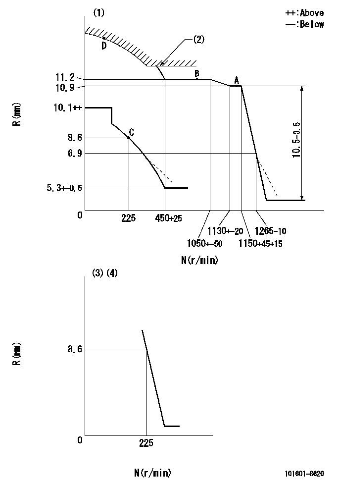
N:Pump speed
R:Rack position (mm)
(1)Beginning of damper spring operation: DL
(2)Excess fuel setting for starting: SXL
(3)Main spring setting
(4)Set the idle spring.
----------
DL=6.5+-0.5mm SXL=12.1+-0.1mm
----------
----------
DL=6.5+-0.5mm SXL=12.1+-0.1mm
----------
Speed control lever angle
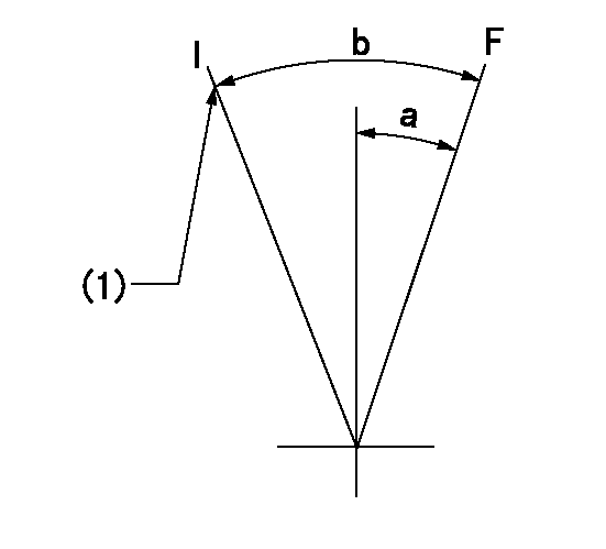
F:Full speed
I:Idle
(1)Stopper bolt setting
----------
----------
a=3deg+-5deg b=(14deg)+-5deg
----------
----------
a=3deg+-5deg b=(14deg)+-5deg
0000000901
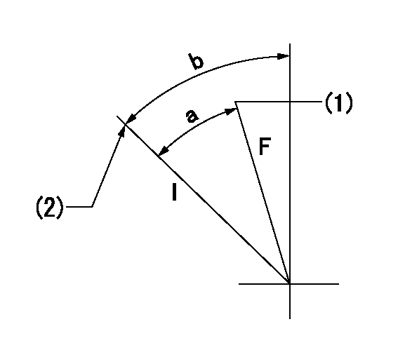
F:Full load
I:Idle
(1)Attach the return spring to the upper hole and adjust.
(2)Stopper bolt setting
----------
----------
a=21deg+-3deg b=30deg+-5deg
----------
----------
a=21deg+-3deg b=30deg+-5deg
Stop lever angle

N:Pump normal
S:Stop the pump.
----------
----------
a=65.5deg+-5deg b=71deg+-5deg
----------
----------
a=65.5deg+-5deg b=71deg+-5deg
Information:
Performance Analysis Report (PAR) Chassis Dynamometer Test
Required Equipment For Test:
Optional Equipment:
Refer to the latest PAR instructions, Special Instruction Form No. SEHS8025, for more detailed instructions concerning preparation of the truck, proper use of the dynamometer and use of the Technical Information File microfiche.Use the following procedure for the PAR Chassis Dynamomenter test:1. Check the fuel API if not done in another procedure. Refer to, Special Instruction, Form No. GMGO0977.2. Record data from the Engine Information Plate.3. Install the required measurement instruments on the engine.4. Operate the engine at partial throttle and load to obtain the normal operating temperature, and then operate the engine at full load for two minutes. While operating at full load, check the fuel pressure [approximately 550 kPa (80 psi)]. If the pressure is low, perform Procedure No. 113T (part of Truck Performance Diagnostic Guide, Form No. SEBD0808), before continuing the test.5. Beginning from Top Engine Limit, load the engine to each test rpm, 5 rpm, for at least two minutes for proper stabilization.6. Record engine test information, in sequence if possible, on the record sheets. If repeat runs are required to complete the sheets, be sure temperatures and conditions are as equal as possible.7.