Information injection-pump assembly
ZEXEL
101601-8590
1016018590
ISUZU
1156015272
1156015272

Rating:
Cross reference number
ZEXEL
101601-8590
1016018590
ISUZU
1156015272
1156015272
Zexel num
Bosch num
Firm num
Name
Calibration Data:
Adjustment conditions
Test oil
1404 Test oil ISO4113 or {SAEJ967d}
1404 Test oil ISO4113 or {SAEJ967d}
Test oil temperature
degC
40
40
45
Nozzle and nozzle holder
105780-8140
Bosch type code
EF8511/9A
Nozzle
105780-0000
Bosch type code
DN12SD12T
Nozzle holder
105780-2080
Bosch type code
EF8511/9
Opening pressure
MPa
17.2
Opening pressure
kgf/cm2
175
Injection pipe
Outer diameter - inner diameter - length (mm) mm 6-2-600
Outer diameter - inner diameter - length (mm) mm 6-2-600
Overflow valve
132424-0620
Overflow valve opening pressure
kPa
157
123
191
Overflow valve opening pressure
kgf/cm2
1.6
1.25
1.95
Tester oil delivery pressure
kPa
157
157
157
Tester oil delivery pressure
kgf/cm2
1.6
1.6
1.6
Direction of rotation (viewed from drive side)
Right R
Right R
Injection timing adjustment
Direction of rotation (viewed from drive side)
Right R
Right R
Injection order
1-5-3-6-
2-4
Pre-stroke
mm
3.6
3.55
3.65
Beginning of injection position
Drive side NO.1
Drive side NO.1
Difference between angles 1
Cal 1-5 deg. 60 59.5 60.5
Cal 1-5 deg. 60 59.5 60.5
Difference between angles 2
Cal 1-3 deg. 120 119.5 120.5
Cal 1-3 deg. 120 119.5 120.5
Difference between angles 3
Cal 1-6 deg. 180 179.5 180.5
Cal 1-6 deg. 180 179.5 180.5
Difference between angles 4
Cyl.1-2 deg. 240 239.5 240.5
Cyl.1-2 deg. 240 239.5 240.5
Difference between angles 5
Cal 1-4 deg. 300 299.5 300.5
Cal 1-4 deg. 300 299.5 300.5
Injection quantity adjustment
Adjusting point
-
Rack position
10.9
Pump speed
r/min
1000
1000
1000
Average injection quantity
mm3/st.
60.3
58.7
61.9
Max. variation between cylinders
%
0
-2.5
2.5
Basic
*
Fixing the rack
*
Standard for adjustment of the maximum variation between cylinders
*
Injection quantity adjustment_02
Adjusting point
H
Rack position
9.5+-0.5
Pump speed
r/min
325
325
325
Average injection quantity
mm3/st.
8.7
7.4
10
Max. variation between cylinders
%
0
-14
14
Fixing the rack
*
Standard for adjustment of the maximum variation between cylinders
*
Injection quantity adjustment_03
Adjusting point
A
Rack position
R1(10.9)
Pump speed
r/min
1000
1000
1000
Average injection quantity
mm3/st.
60.3
59.3
61.3
Basic
*
Fixing the lever
*
Injection quantity adjustment_04
Adjusting point
B
Rack position
R1+0.1
Pump speed
r/min
1600
1600
1600
Average injection quantity
mm3/st.
65.2
63.6
66.8
Fixing the lever
*
Injection quantity adjustment_05
Adjusting point
C
Rack position
R1-0.05
Pump speed
r/min
1300
1300
1300
Average injection quantity
mm3/st.
64
62.4
65.6
Fixing the lever
*
Injection quantity adjustment_06
Adjusting point
D
Rack position
R1(10.9)
Pump speed
r/min
650
650
650
Average injection quantity
mm3/st.
46.9
45.3
48.5
Fixing the lever
*
Timer adjustment
Pump speed
r/min
1050--
Advance angle
deg.
0
0
0
Remarks
Start
Start
Timer adjustment_02
Pump speed
r/min
1000
Advance angle
deg.
0.5
Timer adjustment_03
Pump speed
r/min
1300
Advance angle
deg.
1.8
1.3
2.3
Timer adjustment_04
Pump speed
r/min
1600
Advance angle
deg.
4
3.5
4.5
Remarks
Finish
Finish
Test data Ex:
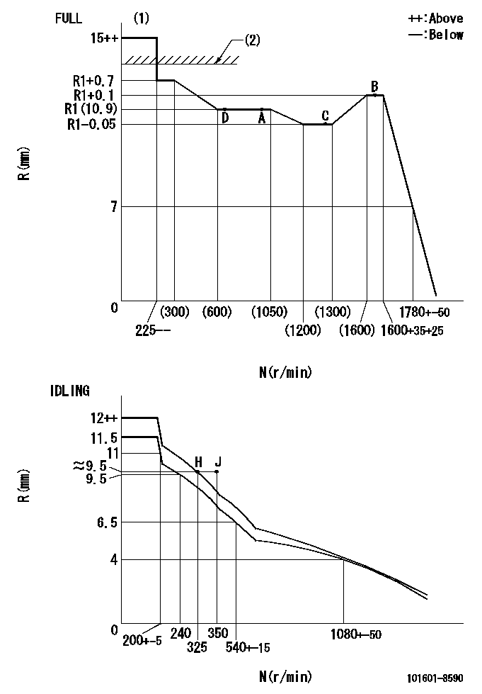
Governor adjustment

N:Pump speed
R:Rack position (mm)
(1)Torque cam stamping: T1
(2)RACK LIMIT: RAL
----------
T1=19 RAL=13.6+0.2mm
----------
----------
T1=19 RAL=13.6+0.2mm
----------
Speed control lever angle

F:Full speed
I:Idle
(1)Use the hole at R = aa
(2)Stopper bolt setting
----------
aa=35mm
----------
a=39deg+-5deg b=39deg+-3deg
----------
aa=35mm
----------
a=39deg+-5deg b=39deg+-3deg
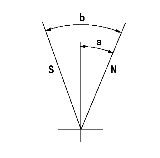
Stop lever angle

N:Pump normal
S:Stop the pump.
----------
----------
a=25deg+-5deg b=40deg+-5deg
----------
----------
a=25deg+-5deg b=40deg+-5deg
Timing setting

(1)Pump vertical direction
(2)Position of timer's threaded hole at No 1 cylinder's beginning of injection
(3)B.T.D.C.: aa
(4)-
----------
aa=14deg
----------
a=(60deg)
----------
aa=14deg
----------
a=(60deg)
Information:
1. Disconnect the batteries. 2. Remove top panel (1), front panel (2) and the rear panel from the enclosure. 3. Remove the bolt holding ground wires (5) to the frame. Remove wire ties (4) to separate the ground wires. Remove two screws and cover (3). 4. Remove three bolts (7) to disconnect the power bars from the main circuit breaker. Remove the insulation material from power bar (6). Remove bolts (8) holding ground bar (9) to the panel. Put identification on the wires for assembly purposes.5. Disconnect wires (10) from the terminal strip. Disconnect wires (11) from the voltage regulator. 6. Disconnect wires (12) from the inside of the control panel. 7. Remove bolts (13) and disconnect the small gage wire from each power bar. 8. Disconnect wire loom (14) from the generator housing and from the inside of the enclosure at three places. Remove the bolts and lower panel (15). Be sure all wires are free from the enclosure 9. Attach tooling (A) and a hoist to the enclosure as shown. Remove four bolts that fasten the enclosure to the base. Remove the enclosure. The weight of the enclosure is 1258 kg (570 lb.). The following steps are for the installation of the control panel enclosure.10. Use a hoist and tooling (A) to put the enclosure in position on the base. Install the four bolts that hold it to the base.11. Connect wire loom (14) to the generator housing and to the inside of the enclosure at three places. Install lower panel (15).12. Connect small gage wire to each power bar with bolts (13).13. Connect wires (12) to the inside of the control panel.14. Connect wires (10) to the terminal strip. Connect wires (11) to the voltage regulator.15. Connect ground bar (9) to the panel with two bolts (8). Wrap insulation material around power bar (6). Connect the power bars to the main circuit breaker with three bolts (7).16. Connect ground wires (5) to the frame and install wire ties (4) to hold the wires together. Install cover (3) with two screws.17. Install the rear, front and top panels on the enclosure.18. Connect the batteries.Remove Control Panel Enclosure (Standby)
The photographs shown are of a 3306B Standby Generator. The procedure is the same for the 3406B Standby Generator. 1. Remove door (1).2. Remove two bolts (2) from cover (3). 3. Remove doors (4).4. Remove fourteen bolts (7) and cover (5).5. Remove the battery charger. See the topic, Remove And Install Battery Charger.6. Remove the bolts and cover (6).7. Remove the three bolts located above the control panel and remove cover (3). 8. Identify and disconnect all the wires from breaker (9) and grounding buss (10).9. Remove bolts (8), bracket (11), and breaker (9). 10. Identify and disconnect all wires (12) between the generator and the control panels from the terminal strips on the control panels.11. Identify and disconnect all wires between the engine and control panels from the terminal strips on the control panels.12. Remove bolts (13). 13.
The photographs shown are of a 3306B Standby Generator. The procedure is the same for the 3406B Standby Generator. 1. Remove door (1).2. Remove two bolts (2) from cover (3). 3. Remove doors (4).4. Remove fourteen bolts (7) and cover (5).5. Remove the battery charger. See the topic, Remove And Install Battery Charger.6. Remove the bolts and cover (6).7. Remove the three bolts located above the control panel and remove cover (3). 8. Identify and disconnect all the wires from breaker (9) and grounding buss (10).9. Remove bolts (8), bracket (11), and breaker (9). 10. Identify and disconnect all wires (12) between the generator and the control panels from the terminal strips on the control panels.11. Identify and disconnect all wires between the engine and control panels from the terminal strips on the control panels.12. Remove bolts (13). 13.