Information injection-pump assembly
ZEXEL
101601-8550
1016018550
ISUZU
1156016081
1156016081

Rating:
Cross reference number
ZEXEL
101601-8550
1016018550
ISUZU
1156016081
1156016081
Zexel num
Bosch num
Firm num
Name
Calibration Data:
Adjustment conditions
Test oil
1404 Test oil ISO4113 or {SAEJ967d}
1404 Test oil ISO4113 or {SAEJ967d}
Test oil temperature
degC
40
40
45
Nozzle and nozzle holder
105780-8140
Bosch type code
EF8511/9A
Nozzle
105780-0000
Bosch type code
DN12SD12T
Nozzle holder
105780-2080
Bosch type code
EF8511/9
Opening pressure
MPa
17.2
Opening pressure
kgf/cm2
175
Injection pipe
Outer diameter - inner diameter - length (mm) mm 6-2-600
Outer diameter - inner diameter - length (mm) mm 6-2-600
Overflow valve
131424-0220
Overflow valve opening pressure
kPa
147
113
181
Overflow valve opening pressure
kgf/cm2
1.5
1.15
1.85
Tester oil delivery pressure
kPa
157
157
157
Tester oil delivery pressure
kgf/cm2
1.6
1.6
1.6
Direction of rotation (viewed from drive side)
Right R
Right R
Injection timing adjustment
Direction of rotation (viewed from drive side)
Right R
Right R
Injection order
1-4-2-6-
3-5
Pre-stroke
mm
3.7
3.65
3.75
Beginning of injection position
Drive side NO.1
Drive side NO.1
Difference between angles 1
Cal 1-4 deg. 60 59.5 60.5
Cal 1-4 deg. 60 59.5 60.5
Difference between angles 2
Cyl.1-2 deg. 120 119.5 120.5
Cyl.1-2 deg. 120 119.5 120.5
Difference between angles 3
Cal 1-6 deg. 180 179.5 180.5
Cal 1-6 deg. 180 179.5 180.5
Difference between angles 4
Cal 1-3 deg. 240 239.5 240.5
Cal 1-3 deg. 240 239.5 240.5
Difference between angles 5
Cal 1-5 deg. 300 299.5 300.5
Cal 1-5 deg. 300 299.5 300.5
Injection quantity adjustment
Adjusting point
A
Rack position
10.9
Pump speed
r/min
1150
1150
1150
Average injection quantity
mm3/st.
106.2
104.2
108.2
Max. variation between cylinders
%
0
-4
4
Fixing the lever
*
Injection quantity adjustment_02
Adjusting point
B
Rack position
11.2
Pump speed
r/min
700
700
700
Average injection quantity
mm3/st.
108.1
107.1
109.1
Max. variation between cylinders
%
0
-2
2
Basic
*
Fixing the lever
*
Injection quantity adjustment_03
Adjusting point
C
Rack position
8.6+-0.5
Pump speed
r/min
225
225
225
Average injection quantity
mm3/st.
11.5
9.2
13.8
Max. variation between cylinders
%
0
-13
13
Fixing the rack
*
Injection quantity adjustment_04
Adjusting point
D
Rack position
-
Pump speed
r/min
150
150
150
Each cylinder's injection qty
mm3/st.
140
140
Fixing the lever
*
Remarks
After startup boost setting
After startup boost setting
Injection quantity adjustment_05
Adjusting point
E
Rack position
9.8
Pump speed
r/min
700
700
700
Average injection quantity
mm3/st.
73
71
75
Max. variation between cylinders
%
0
-2
2
Fixing the lever
*
Remarks
At absolute pressure 61.3 kPa {460 mmHg}
At absolute pressure 61.3 kPa {460 mmHg}
Timer adjustment
Pump speed
r/min
500
Advance angle
deg.
0.3
Timer adjustment_02
Pump speed
r/min
600
Advance angle
deg.
0.8
0.1
0.8
Timer adjustment_03
Pump speed
r/min
700
Advance angle
deg.
0.8
0.3
1.3
Timer adjustment_04
Pump speed
r/min
900
Advance angle
deg.
2
1.5
2.5
Timer adjustment_05
Pump speed
r/min
1150
Advance angle
deg.
4
3.5
4.5
Remarks
Finish
Finish
Test data Ex:
Governor adjustment
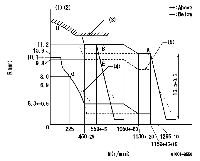
N:Pump speed
R:Rack position (mm)
(1)Lever ratio: RT
(2)Target shim dimension: TH
(3)Excess fuel setting for starting: SXL
(4)Damper spring setting: DL
(5)Aneroid compensator absolute pressure: P1
----------
RT=1 TH=1.5mm SXL=12.1+-0.1mm DL=6.5+-0.5mm P1=61.3+-0.7kPa(460+-5mmHg)
----------
----------
RT=1 TH=1.5mm SXL=12.1+-0.1mm DL=6.5+-0.5mm P1=61.3+-0.7kPa(460+-5mmHg)
----------
Speed control lever angle
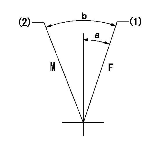
F:Full speed
M:Minimum-maximum speed
(1)Set the pump speed at aa. ( At delivery )
(2)Pump speed = bb
----------
aa=1150r/min bb=550r/min
----------
a=3deg+-5deg b=11deg+-5deg
----------
aa=1150r/min bb=550r/min
----------
a=3deg+-5deg b=11deg+-5deg
0000000901
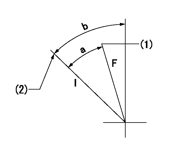
F:Full load
I:Idle
(1)Attach the return spring to the upper hole and adjust.
(2)Stopper bolt setting
----------
----------
a=21deg+-3deg b=30deg+-5deg
----------
----------
a=21deg+-3deg b=30deg+-5deg
Stop lever angle

N:Pump normal
S:Stop the pump.
----------
----------
a=65.5deg+-5deg b=71deg+-5deg
----------
----------
a=65.5deg+-5deg b=71deg+-5deg
0000001501 ACS
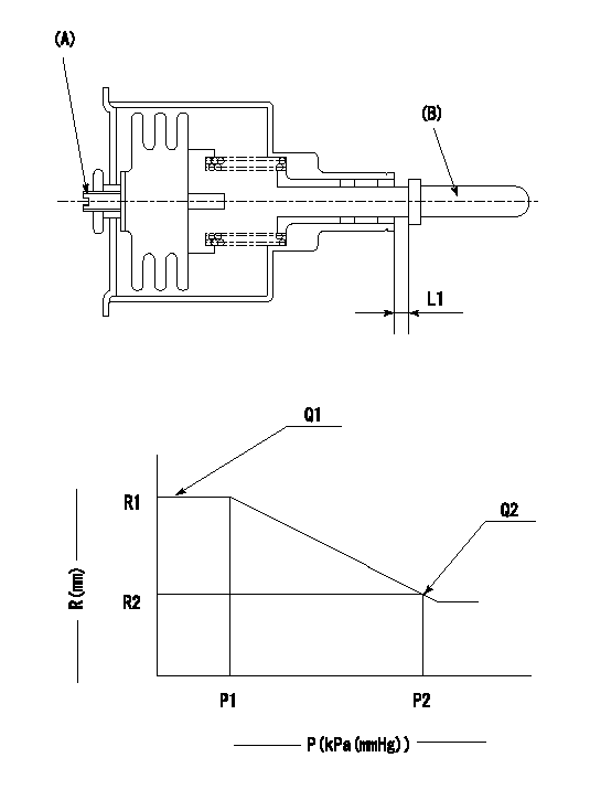
(A) Set screw
(B) Push rod 1
1. Aneroid compensator unit adjustment
(1)Screw in (A) to obtain L1.
2. Adjustment following governor installation
(1)Set the speed of the pump to N1 r/min and fix the control lever at the full set position.
(2)Screw in the aneroid compensator to obtain the performance shown in the graph above.
----------
N1=700r/min L1=(0.6~0.9)mm
----------
R1=11.2mm R2=9.8mm P1=(90.6)kPa((680)mmHg) P2=61.3+-0.7kPa(460+-5mmHg) Q1=108.1+-1cm3/1000st Q2=(73)+-1cm3/1000st
----------
N1=700r/min L1=(0.6~0.9)mm
----------
R1=11.2mm R2=9.8mm P1=(90.6)kPa((680)mmHg) P2=61.3+-0.7kPa(460+-5mmHg) Q1=108.1+-1cm3/1000st Q2=(73)+-1cm3/1000st
Timing setting

(1)Pump vertical direction
(2)Position of timer's threaded hole at No 1 cylinder's beginning of injection
(3)B.T.D.C.: aa
(4)-
----------
aa=17deg
----------
a=(60deg)
----------
aa=17deg
----------
a=(60deg)
Information:
Start By:a. remove valve covers 1. Use tooling (A), and disconnect fuel line (1) at each end. Remove the fuel line from the engine. 2. Use tool (B), and remove retainer (2) from the adapter.3. Remove the fuel injection nozzles with tooling (C) as follows:a. Install the 6V6983 Adapter and the 8T3199 Screw into nozzle assembly (3).b. Install the 8T3198 Tube over the 8T3199 Screw.c. Use the 1B4206 Nut on the 8T3199 Screw.c. Use the 1B4206 Nut on the 8T3199 Screw to pull the fuel injection nozzle from the adapter.4. Remove compression seal (4) and carbon dam seal (8) from fuel injection nozzle (3).5. Use tool (D), and remove adapter (6) from the cylinder head.6. Remove gasket (7) and seal (5) from adapter (6). The following steps are for installation of the fuel injection nozzles and adapters.7. Use tool (E) to clean the bore in adapter (6). Use an open end wrench or tap driver to turn tool (E).8. Inspect seal (5) for damage or wear. Replace the seal if necessary.9. Put washer (7) and seal (5) in position on adapter (6).10. Put liquid soap in the bores of the cylinder head and on seals (5) in the adapters.11. Put 5P3931 Anti-Seize Compound on the threads of adapter (6), and install the adapter in the cylinder head assembly.12. Use tool (D), and tighten the adapter to a torque of 205 14 N m (150 10 lb.ft.).
Make sure the correct compression seal washer (4) is used when the nozzle assembly is installed in the adapter. Only copper washers are to be used with this adapter.
13. Install compression seal washer (4), and use tool (F) to install carbon dam seal (8) on the fuel injection nozzle.14. Put fuel injection nozzle (3) in position in the adapter, and install retainer (2).15. Use tool (B) to tighten retainer (2) to a torque of 48 7 N m (35 5 lb.ft.).16. Install fuel line (1). Tighten the nuts on the fuel line with tooling (A) to a torque of 40 7 N m (30 5 lb.ft.).End By:a. install valve covers