Information injection-pump assembly
ZEXEL
101601-8032
1016018032
ISUZU
1156013022
1156013022

Rating:
Service parts 101601-8032 INJECTION-PUMP ASSEMBLY:
1.
_
7.
COUPLING PLATE
8.
_
9.
_
11.
Nozzle and Holder
1-15300-104-2
12.
Open Pre:MPa(Kqf/cm2)
18.1{185}

15.
NOZZLE SET
Cross reference number
ZEXEL
101601-8032
1016018032
ISUZU
1156013022
1156013022
Zexel num
Bosch num
Firm num
Name
Calibration Data:
Adjustment conditions
Test oil
1404 Test oil ISO4113 or {SAEJ967d}
1404 Test oil ISO4113 or {SAEJ967d}
Test oil temperature
degC
40
40
45
Nozzle and nozzle holder
105780-8140
Bosch type code
EF8511/9A
Nozzle
105780-0000
Bosch type code
DN12SD12T
Nozzle holder
105780-2080
Bosch type code
EF8511/9
Opening pressure
MPa
17.2
Opening pressure
kgf/cm2
175
Injection pipe
Outer diameter - inner diameter - length (mm) mm 6-2-600
Outer diameter - inner diameter - length (mm) mm 6-2-600
Overflow valve
132424-0620
Overflow valve opening pressure
kPa
157
123
191
Overflow valve opening pressure
kgf/cm2
1.6
1.25
1.95
Tester oil delivery pressure
kPa
157
157
157
Tester oil delivery pressure
kgf/cm2
1.6
1.6
1.6
Direction of rotation (viewed from drive side)
Right R
Right R
Injection timing adjustment
Direction of rotation (viewed from drive side)
Right R
Right R
Injection order
1-5-3-6-
2-4
Pre-stroke
mm
3.6
3.55
3.65
Beginning of injection position
Drive side NO.1
Drive side NO.1
Difference between angles 1
Cal 1-5 deg. 60 59.5 60.5
Cal 1-5 deg. 60 59.5 60.5
Difference between angles 2
Cal 1-3 deg. 120 119.5 120.5
Cal 1-3 deg. 120 119.5 120.5
Difference between angles 3
Cal 1-6 deg. 180 179.5 180.5
Cal 1-6 deg. 180 179.5 180.5
Difference between angles 4
Cyl.1-2 deg. 240 239.5 240.5
Cyl.1-2 deg. 240 239.5 240.5
Difference between angles 5
Cal 1-4 deg. 300 299.5 300.5
Cal 1-4 deg. 300 299.5 300.5
Injection quantity adjustment
Adjusting point
-
Rack position
12.7
Pump speed
r/min
1000
1000
1000
Average injection quantity
mm3/st.
78
76.4
79.6
Max. variation between cylinders
%
0
-2.5
2.5
Basic
*
Fixing the rack
*
Standard for adjustment of the maximum variation between cylinders
*
Injection quantity adjustment_02
Adjusting point
H
Rack position
9.5+-0.5
Pump speed
r/min
260
260
260
Average injection quantity
mm3/st.
8.1
6.8
9.4
Max. variation between cylinders
%
0
-14
14
Fixing the rack
*
Standard for adjustment of the maximum variation between cylinders
*
Injection quantity adjustment_03
Adjusting point
A
Rack position
R1(12.7)
Pump speed
r/min
1000
1000
1000
Average injection quantity
mm3/st.
78
77
79
Basic
*
Fixing the lever
*
Injection quantity adjustment_04
Adjusting point
I
Rack position
15+-0.5
Pump speed
r/min
150
150
150
Average injection quantity
mm3/st.
92
92
100
Fixing the lever
*
Rack limit
*
Timer adjustment
Pump speed
r/min
1350--
Advance angle
deg.
0
0
0
Remarks
Start
Start
Timer adjustment_02
Pump speed
r/min
1300
Advance angle
deg.
0.5
Timer adjustment_03
Pump speed
r/min
1400
Advance angle
deg.
2
1.5
2.5
Timer adjustment_04
Pump speed
r/min
1500
Advance angle
deg.
4.5
4
5
Remarks
Finish
Finish
Test data Ex:
Governor adjustment
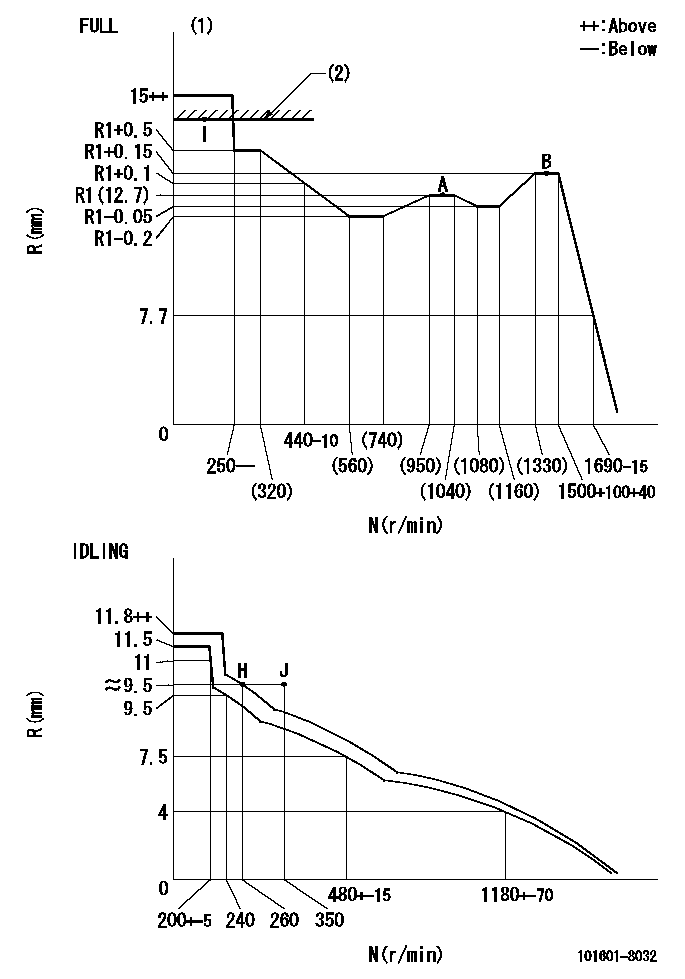
N:Pump speed
R:Rack position (mm)
(1)Torque cam stamping: T1
(2)RACK LIMIT
----------
T1=78
----------
----------
T1=78
----------
Speed control lever angle
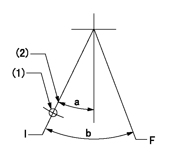
F:Full speed
I:Idle
(1)Use the hole at R = aa
(2)Stopper bolt setting
----------
aa=45mm
----------
a=21.5deg+-5deg b=(45deg)+-3deg
----------
aa=45mm
----------
a=21.5deg+-5deg b=(45deg)+-3deg
Stop lever angle

N:Pump normal
S:Stop the pump.
----------
----------
a=25deg+-5deg b=40deg+-5deg
----------
----------
a=25deg+-5deg b=40deg+-5deg
Timing setting

(1)Pump vertical direction
(2)Position of timer's threaded hole at No 1 cylinder's beginning of injection
(3)-
(4)-
----------
----------
a=(60deg)
----------
----------
a=(60deg)
Information:
B. Back out (loosen) the lift adjustment screw 3/4 1/8of a turn.C. Put the nozzle in a vise with 8S2250 Holding Tool (1). Hold pressure adjusting screw (4) and tighten the locknut to a torque of 8.0-8.5 N m (70-75 lb in) using the 2P5487 Adapter (A). Recheck the opening pressure.Adjustment of 9L7883 Nozzles
1. Remove the nozzle from the tester and place in a vise using 8S2250 Nozzle Holding Tool (1). Loosen lift adjusting screw locknut (2). Loosen lift adjusting screw (3) two full turns counterclockwise.
If lift adjusting screw (3) is not loosened, the valve can be damaged in later steps.
2. Loosen pressure adjusting screw (4) and remove the nozzle from the nozzle holding tool. 3. Tilt the nozzle slightly down from the vertical position and remove pressure screw (4) and shims (5). If the shims do not come out of the nozzle, invert the nozzle and let the shims, spring and spring seat fall into the hand. If the valve comes out of its own weight, handle it carefully by its stem.4. To increase the opening pressure, add a 4N5730 Shim. The 4N5730 Shim is 0.13 mm (.005") thick and will increase the opening pressure approximately 1725 kPa (250 psi). A maximum of two shims can be added; if two shims do not increase opening pressure to specification given, discard the nozzle. 5. Assemble the nozzle, making sure the thickest shim (C) is against pressure screw (4). Put the nozzle in a vise using 8S2250 Nozzle Holding Tool (1). Tighten the pressure adjusting screw to 8.0-9.1 N m (70-80 lb in) torque.6. Remove the nozzle from the holding tool. Connect the nozzle, with the tip facing downward, to the tester. Point the nozzle tip into the 8S2270 Fuel Collector and the FT1384 Extension. Check the opening pressure and if it is not within specifications, repeat steps 4 and 5.Valve Lift Adjustment-9L7883 Nozzles
A. When the correct opening pressure is set, and while pumping test fluid through the nozzle, hold the lift adjusting screw locknut and slowly turn the lift adjusting screw clockwise (CW) until valve pressure rises 1380-3450 kPa (200-500 psi) above the nozzle opening pressure. Some test fluid may collect on the tip, but it must not flow at a rapid dribble.
Do not bend the valve by bottoming with too much force.
B. Back out the lift screw 3/4 1/8 turn, hold the lift adjusting screw, and tighten the locknut just enough so the screw will not turn; the lift is now set. C. Put the nozzle in a vise using 8S2250 Holding Tool (1). Tighten the locknut to 4.0-4.5 N m (35-40 lb in). Recheck valve opening pressure.Adjustment of 9L6969, 7N0449, 9N3299, 9N3700, 9N3979, 1W5829, 4W1819, 4W8483 and 7W3710 Nozzles
1. Put the nozzle in a vise using the 8S2250 Holding Tool (1). Loosen lift adjusting screw locknut (2). Turn lift adjusting screw (3) two full turns counterclockwise (CCW). 2. Hold lift adjusting screw (3) with a .08 mm (5/64") hex wrench (4) and