Information injection-pump assembly
ZEXEL
101601-7550
1016017550
ISUZU
1156010681
1156010681

Rating:
Service parts 101601-7550 INJECTION-PUMP ASSEMBLY:
1.
_
7.
COUPLING PLATE
8.
_
9.
_
11.
Nozzle and Holder
1-15300-103-2
12.
Open Pre:MPa(Kqf/cm2)
22.1{225}
15.
NOZZLE SET
Cross reference number
ZEXEL
101601-7550
1016017550
ISUZU
1156010681
1156010681
Zexel num
Bosch num
Firm num
Name
101601-7550
1156010681 ISUZU
INJECTION-PUMP ASSEMBLY
6QA2 * K 14BF PE6AD PE
6QA2 * K 14BF PE6AD PE
Calibration Data:
Adjustment conditions
Test oil
1404 Test oil ISO4113 or {SAEJ967d}
1404 Test oil ISO4113 or {SAEJ967d}
Test oil temperature
degC
40
40
45
Nozzle and nozzle holder
105780-8140
Bosch type code
EF8511/9A
Nozzle
105780-0000
Bosch type code
DN12SD12T
Nozzle holder
105780-2080
Bosch type code
EF8511/9
Opening pressure
MPa
17.2
Opening pressure
kgf/cm2
175
Injection pipe
Outer diameter - inner diameter - length (mm) mm 6-2-600
Outer diameter - inner diameter - length (mm) mm 6-2-600
Overflow valve
132424-0620
Overflow valve opening pressure
kPa
147
113
181
Overflow valve opening pressure
kgf/cm2
1.5
1.15
1.85
Tester oil delivery pressure
kPa
157
157
157
Tester oil delivery pressure
kgf/cm2
1.6
1.6
1.6
Direction of rotation (viewed from drive side)
Right R
Right R
Injection timing adjustment
Direction of rotation (viewed from drive side)
Right R
Right R
Injection order
1-4-2-6-
3-5
Pre-stroke
mm
3.7
3.65
3.75
Beginning of injection position
Drive side NO.1
Drive side NO.1
Difference between angles 1
Cal 1-4 deg. 60 59.5 60.5
Cal 1-4 deg. 60 59.5 60.5
Difference between angles 2
Cyl.1-2 deg. 120 119.5 120.5
Cyl.1-2 deg. 120 119.5 120.5
Difference between angles 3
Cal 1-6 deg. 180 179.5 180.5
Cal 1-6 deg. 180 179.5 180.5
Difference between angles 4
Cal 1-3 deg. 240 239.5 240.5
Cal 1-3 deg. 240 239.5 240.5
Difference between angles 5
Cal 1-5 deg. 300 299.5 300.5
Cal 1-5 deg. 300 299.5 300.5
Injection quantity adjustment
Adjusting point
A
Rack position
11.2
Pump speed
r/min
1150
1150
1150
Average injection quantity
mm3/st.
111.5
109.5
113.5
Max. variation between cylinders
%
0
-4
4
Fixing the lever
*
Injection quantity adjustment_02
Adjusting point
B
Rack position
11.6
Pump speed
r/min
700
700
700
Average injection quantity
mm3/st.
115
114
116
Max. variation between cylinders
%
0
-2
2
Basic
*
Fixing the lever
*
Injection quantity adjustment_03
Adjusting point
C
Rack position
8.6+-0.5
Pump speed
r/min
225
225
225
Average injection quantity
mm3/st.
11.5
9.2
13.8
Max. variation between cylinders
%
0
-13
13
Fixing the rack
*
Injection quantity adjustment_04
Adjusting point
D
Rack position
14.2+-0.
5
Pump speed
r/min
150
150
150
Average injection quantity
mm3/st.
140
140
Fixing the lever
*
Remarks
After startup boost setting
After startup boost setting
Timer adjustment
Pump speed
r/min
925
Advance angle
deg.
0.3
Timer adjustment_02
Pump speed
r/min
975
Advance angle
deg.
1.4
0.1
1.4
Timer adjustment_03
Pump speed
r/min
1050
Advance angle
deg.
2.4
1.9
2.9
Timer adjustment_04
Pump speed
r/min
1150
Advance angle
deg.
5
4.5
5.5
Remarks
Finish
Finish
Test data Ex:
Governor adjustment
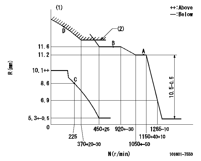
N:Pump speed
R:Rack position (mm)
(1)Beginning of damper spring operation: DL
(2)Excess fuel setting for starting: SXL
----------
DL=6.5+-0.5mm SXL=12.4+-0.1mm
----------
----------
DL=6.5+-0.5mm SXL=12.4+-0.1mm
----------
0000000901
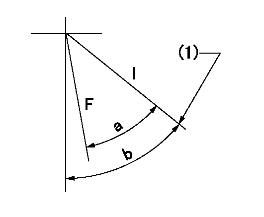
F:Full load
I:Idle
(1)Stopper bolt setting
----------
----------
a=22deg+-3deg b=55deg+-5deg
----------
----------
a=22deg+-3deg b=55deg+-5deg
Stop lever angle
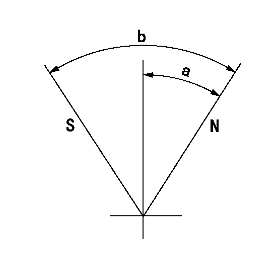
N:Pump normal
S:Stop the pump.
----------
----------
a=35.5deg+-5deg b=71deg+-5deg
----------
----------
a=35.5deg+-5deg b=71deg+-5deg
0000001501 MICRO SWITCH
Adjustment of the micro-switch
Adjust the bolt to obtain the following lever position when the micro-switch is ON.
(1)Speed N1
(2)Rack position Ra
----------
N1=375r/min Ra=8.6mm
----------
----------
N1=375r/min Ra=8.6mm
----------
Information:
Coolant is essential to control engine operating temperatures and make components last longer. Poorly maintained coolant can actually shorten component life by causing a chain reaction of heat problems. Excessive heat can cause: * Hot spots that crack steel, notably in cylinder heads* Bubble pockets that form on cylinder surfaces and result in liner pitting* Oil to degrade, leading to component damage* Lacquer and shellac build-up on precision hydraulic parts* Oil additives to break down and transmission clutches to slipS O S Coolant Analysis is the best way to monitor the condition of your coolant and your cooling system. The two-level program, based on samples you submit, shows the condition of coolant and the cooling system.Level I: Basic Coolant Maintenance Check
Checks for correct chemical balance for proper heat and corrosion control. Tests for: * glycol* SCA concentrations* pH* conductivityS O S Coolant Analysis reports results and makes recommendations, usually within 24 hours. Consult with your Caterpillar dealer for more information.The concentration of SCA should be checked regularly for over or under concentration. This should be done with the 4C-9301 Test Kit or the 8T-5296 Test Kit or S O S Coolant Analysis (Level I) at the Every 250 Hours interval.Further coolant analysis is recommended at twice a year or after every 1000 service hours.For example, suppose considerable deposits are found in the water jacket areas on the external cooling system, yet coolant additive concentrations were carefully maintained. Chances are that the coolant water had minerals which deposited on the engine over time.One way to verify the water condition, or to be sure of new water at fill time, is to have a coolant analysis conducted. Full water analysis can sometimes be obtained locally by contacting your local water utility company or an agricultural agent. Private laboratories are also available.Caterpillar recommends S O S Level II Coolant Analysis.Level II: Comprehensive Cooling System Analysis
Completely analyzes coolant and coolant effects on the cooling system. Level II Coolant Analysis provides: * full Level I analysis* visual properties inspection* metal corrosion and contaminant identification* identification of built-up impurities that point to corrosion and scaling problems BEFORE they lead to costly repairsLevel II Coolant Analysis provides a simple, clear report of results, and makes recommendations for the lowest cost corrective options.For more information on coolant analysis and how it can help you manage your equipment, see your Caterpillar dealer.
Have questions with 101601-7550?
Group cross 101601-7550 ZEXEL
Isuzu
101601-7550
1156010681
INJECTION-PUMP ASSEMBLY
6QA2
6QA2