Information injection-pump assembly
BOSCH
9 400 610 081
9400610081
ZEXEL
101601-6781
1016016781
MITSUBISHI
ME036846
me036846

Rating:
Service parts 101601-6781 INJECTION-PUMP ASSEMBLY:
1.
_
6.
COUPLING PLATE
7.
COUPLING PLATE
8.
_
9.
_
11.
Nozzle and Holder
ME036780
12.
Open Pre:MPa(Kqf/cm2)
21.6{220}

15.
NOZZLE SET
Cross reference number
BOSCH
9 400 610 081
9400610081
ZEXEL
101601-6781
1016016781
MITSUBISHI
ME036846
me036846
Zexel num
Bosch num
Firm num
Name
101601-6781
9 400 610 081
ME036846 MITSUBISHI
INJECTION-PUMP ASSEMBLY
6D14 K
6D14 K
Calibration Data:
Adjustment conditions
Test oil
1404 Test oil ISO4113 or {SAEJ967d}
1404 Test oil ISO4113 or {SAEJ967d}
Test oil temperature
degC
40
40
45
Nozzle and nozzle holder
105780-8140
Bosch type code
EF8511/9A
Nozzle
105780-0000
Bosch type code
DN12SD12T
Nozzle holder
105780-2080
Bosch type code
EF8511/9
Opening pressure
MPa
17.2
Opening pressure
kgf/cm2
175
Injection pipe
Outer diameter - inner diameter - length (mm) mm 6-2-600
Outer diameter - inner diameter - length (mm) mm 6-2-600
Overflow valve
131424-3720
Overflow valve opening pressure
kPa
255
221
289
Overflow valve opening pressure
kgf/cm2
2.6
2.25
2.95
Tester oil delivery pressure
kPa
157
157
157
Tester oil delivery pressure
kgf/cm2
1.6
1.6
1.6
Direction of rotation (viewed from drive side)
Left L
Left L
Injection timing adjustment
Direction of rotation (viewed from drive side)
Left L
Left L
Injection order
1-5-3-6-
2-4
Pre-stroke
mm
3.3
3.25
3.35
Beginning of injection position
Governor side NO.1
Governor side NO.1
Difference between angles 1
Cal 1-5 deg. 60 59.5 60.5
Cal 1-5 deg. 60 59.5 60.5
Difference between angles 2
Cal 1-3 deg. 120 119.5 120.5
Cal 1-3 deg. 120 119.5 120.5
Difference between angles 3
Cal 1-6 deg. 180 179.5 180.5
Cal 1-6 deg. 180 179.5 180.5
Difference between angles 4
Cyl.1-2 deg. 240 239.5 240.5
Cyl.1-2 deg. 240 239.5 240.5
Difference between angles 5
Cal 1-4 deg. 300 299.5 300.5
Cal 1-4 deg. 300 299.5 300.5
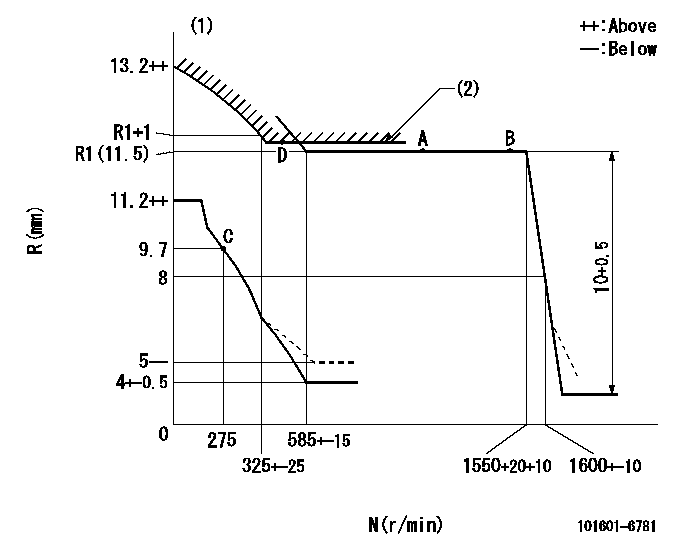
Injection quantity adjustment
Adjusting point
-
Rack position
11.5
Pump speed
r/min
850
850
850
Each cylinder's injection qty
mm3/st.
61.5
59.7
63.3
Basic
*
Fixing the rack
*
Standard for adjustment of the maximum variation between cylinders
*
Injection quantity adjustment_02
Adjusting point
C
Rack position
9.7+-0.5
Pump speed
r/min
275
275
275
Each cylinder's injection qty
mm3/st.
10.5
9
12
Fixing the rack
*
Standard for adjustment of the maximum variation between cylinders
*
Injection quantity adjustment_03
Adjusting point
A
Rack position
R1(11.5)
Pump speed
r/min
850
850
850
Average injection quantity
mm3/st.
61.5
60.5
62.5
Fixing the lever
*
Injection quantity adjustment_04
Adjusting point
B
Rack position
R1(11.5)
Pump speed
r/min
1500
1500
1500
Average injection quantity
mm3/st.
65.8
63.1
68.5
Difference in delivery
mm3/st.
5.4
5.4
5.4
Fixing the lever
*
Timer adjustment
Pump speed
r/min
850+-50
Advance angle
deg.
0
0
0
Remarks
Start
Start
Timer adjustment_02
Pump speed
r/min
1200
Advance angle
deg.
2.6
2.1
3.1
Timer adjustment_03
Pump speed
r/min
1500
Advance angle
deg.
5.5
5
6
Remarks
Finish
Finish
Test data Ex:
Governor adjustment
N:Pump speed
R:Rack position (mm)
(1)Beginning of damper spring operation: DL
(2)Excess fuel setting for starting: SXL
----------
DL=6.5-0.2mm SXL=R1+1+0.8mm
----------
----------
DL=6.5-0.2mm SXL=R1+1+0.8mm
----------
Speed control lever angle

F:Full speed
----------
----------
a=13deg+-5deg
----------
----------
a=13deg+-5deg
0000000901
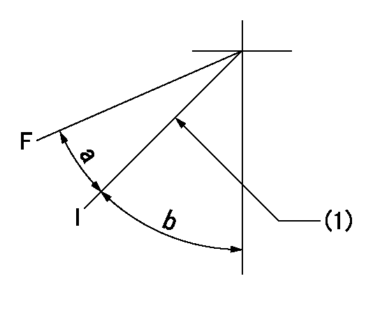
F:Full load
I:Idle
(1)Stopper bolt setting
----------
----------
a=27deg+-5deg b=57deg+-5deg
----------
----------
a=27deg+-5deg b=57deg+-5deg
Stop lever angle
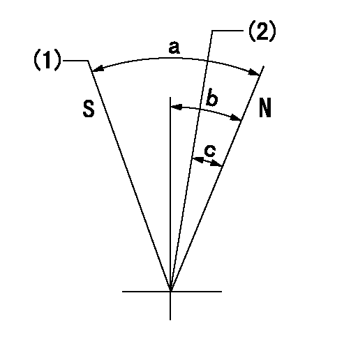
N:Pump normal
S:Stop the pump.
(1)Rack position = aa
(2)Rack position bb
----------
aa=2.5mm bb=21mm
----------
a=71deg+-5deg b=20deg+-5deg c=(9.5deg)
----------
aa=2.5mm bb=21mm
----------
a=71deg+-5deg b=20deg+-5deg c=(9.5deg)
Timing setting

(1)Pump vertical direction
(2)Position of gear mark '2' at No 1 cylinder's beginning of injection
(3)B.T.D.C.: aa
(4)-
----------
aa=16deg
----------
a=(90deg)
----------
aa=16deg
----------
a=(90deg)
Information:
Coolant
To prevent personal injury, do not step up on engine to remove the filler cap, if applicable. Use an adequate ladder.At operating temperature, the engine coolant is hot and under pressure. The radiator and all lines to heaters or the engine contain hot water. When pressure is relieved rapidly, this hot water can turn into steam.Allow cooling system components to cool before draining.Any contact with hot water or steam can cause severe burns.Check the coolant level only after the engine has been stopped and the filler cap is cool enough to remove with your bare hand.Remove the cooling system filler cap slowly to relieve pressure.Cooling system supplemental additive contains alkali. To prevent personal injury, avoid contact with the skin and eyes and do not drink.Oils
Hot oil and components can cause personal injury. Do not allow hot oil or components to contact the skin.Batteries
Battery electrolyte contains acid and can cause injury. Avoid contact with the skin and eyes.Wash hands after touching batteries and connectors. Use of gloves is recommended.Batteries give off flammable fumes which can explode.Always thaw a frozen battery before jump starting. Frozen batteries can explode.Do not smoke when observing the battery electrolyte levels.Always wear protective glasses when working with batteries.Fire or Explosion Prevention
Determine whether the engine will be operated in an environment in which combustible gases could be drawn through the air inlet system. These gases could cause the engine to overspeed, which in turn could seriously damage the engine and result in bodily injury or property damage.If your application involves the presence of combustible gases, consult your Caterpillar dealer to obtain additional information concerning protection devices suitable for the application involved.Inhaling freon gas through a lit cigarette or other smoking method, or inhaling fumes released from a flame contacting freon could cause bodily harm or death. Do not smoke when servicing, charging or working around air conditioners or where freon gas may be present.All fuels, most lubricants and some coolant mixtures are flammable.Diesel fuel is flammable. Gasoline is flammable. The mixture of diesel and gasoline fumes are extremely explosive.Do not smoke while refueling or in a refueling area.Always thaw a frozen battery before jump starting. Frozen batteries can explode.Do not smoke in areas where batteries are charged, or where flammable materials are stored.Batteries give off flammable fumes which can explode.Keep all fuels and lubricants stored in properly marked containers and away from all unauthorized persons.Store all oily rags or other flammable material in a protective container, in a safe place.Do not weld or flame cut on pipes or tubes that contain flammable fluids. Clean them thoroughly with nonflammable solvent before welding or flame cutting on them.Remove all flammable materials such as fuel, oil and other debris before they accumulate on the truck engine.Do not expose the engine to flames, burning brush, etc., if at all possible.Exhaust shields (if equipped), which protect hot exhaust components from oil or fuel spray in the event of a line, tube or seal failure, must be installed correctly.Never disconnect any charging
Have questions with 101601-6781?
Group cross 101601-6781 ZEXEL
Mitsubishi
101601-6781
9 400 610 081
ME036846
INJECTION-PUMP ASSEMBLY
6D14
6D14