Information injection-pump assembly
ZEXEL
101601-6150
1016016150
MITSUBISHI
3096142010
3096142010
Rating:
Cross reference number
ZEXEL
101601-6150
1016016150
MITSUBISHI
3096142010
3096142010
Zexel num
Bosch num
Firm num
Name
Calibration Data:
Adjustment conditions
Test oil
1404 Test oil ISO4113 or {SAEJ967d}
1404 Test oil ISO4113 or {SAEJ967d}
Test oil temperature
degC
40
40
45
Nozzle and nozzle holder
105780-8140
Bosch type code
EF8511/9A
Nozzle
105780-0000
Bosch type code
DN12SD12T
Nozzle holder
105780-2080
Bosch type code
EF8511/9
Opening pressure
MPa
17.2
Opening pressure
kgf/cm2
175
Injection pipe
Outer diameter - inner diameter - length (mm) mm 6-2-600
Outer diameter - inner diameter - length (mm) mm 6-2-600
Overflow valve
132424-0620
Overflow valve opening pressure
kPa
157
123
191
Overflow valve opening pressure
kgf/cm2
1.6
1.25
1.95
Tester oil delivery pressure
kPa
157
157
157
Tester oil delivery pressure
kgf/cm2
1.6
1.6
1.6
Direction of rotation (viewed from drive side)
Right R
Right R
Injection timing adjustment
Direction of rotation (viewed from drive side)
Right R
Right R
Injection order
1-5-3-6-
2-4
Pre-stroke
mm
2.2
2.15
2.25
Beginning of injection position
Governor side NO.1
Governor side NO.1
Difference between angles 1
Cal 1-5 deg. 60 59.5 60.5
Cal 1-5 deg. 60 59.5 60.5
Difference between angles 2
Cal 1-3 deg. 120 119.5 120.5
Cal 1-3 deg. 120 119.5 120.5
Difference between angles 3
Cal 1-6 deg. 180 179.5 180.5
Cal 1-6 deg. 180 179.5 180.5
Difference between angles 4
Cyl.1-2 deg. 240 239.5 240.5
Cyl.1-2 deg. 240 239.5 240.5
Difference between angles 5
Cal 1-4 deg. 300 299.5 300.5
Cal 1-4 deg. 300 299.5 300.5
Injection quantity adjustment
Adjusting point
A
Rack position
11
Pump speed
r/min
1200
1200
1200
Average injection quantity
mm3/st.
112
107.3
116.7
Max. variation between cylinders
%
0
-4
4
Fixing the lever
*
Injection quantity adjustment_02
Adjusting point
B
Rack position
11
Pump speed
r/min
800
800
800
Average injection quantity
mm3/st.
112.3
109.9
114.7
Max. variation between cylinders
%
0
-3
3
Basic
*
Fixing the rack
*
Injection quantity adjustment_03
Adjusting point
C
Rack position
7.2+-0.5
Pump speed
r/min
200
200
200
Average injection quantity
mm3/st.
10.7
8.1
13.3
Max. variation between cylinders
%
0
-15
15
Fixing the rack
*
Injection quantity adjustment_04
Adjusting point
D
Rack position
12.8+-0.
5
Pump speed
r/min
100
100
100
Average injection quantity
mm3/st.
113
113
Fixing the lever
*
Remarks
After startup boost setting
After startup boost setting
Timer adjustment
Pump speed
r/min
400+-50
Advance angle
deg.
0
0
0
Remarks
Start
Start
Timer adjustment_02
Pump speed
r/min
800
Advance angle
deg.
1.8
1.3
2.3
Timer adjustment_03
Pump speed
r/min
1250
Advance angle
deg.
4
3.5
4.5
Remarks
Finish
Finish
Test data Ex:
Governor adjustment
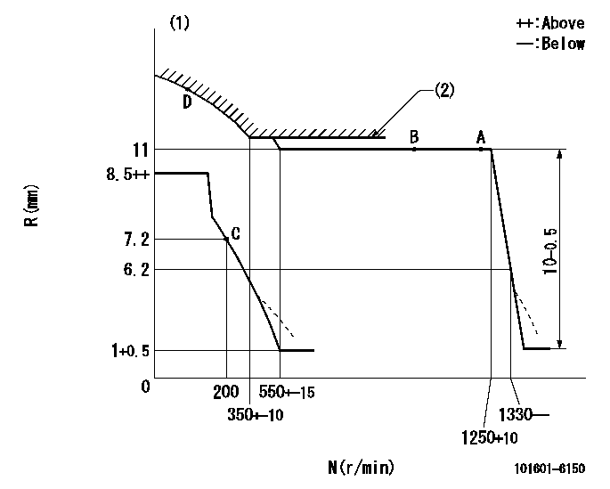
N:Pump speed
R:Rack position (mm)
(1)Beginning of damper spring operation: DL
(2)Excess fuel setting for starting: SXL
----------
DL=4.5-0.2mm SXL=11+0.2mm
----------
----------
DL=4.5-0.2mm SXL=11+0.2mm
----------
0000000901
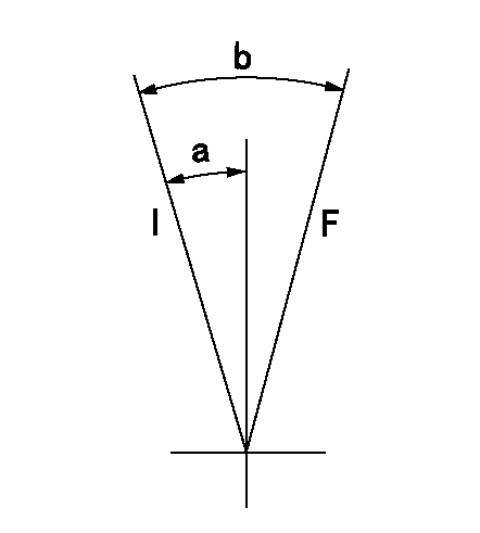
F:Full load
I:Idle
----------
----------
a=16deg+-5deg b=36deg+-3deg
----------
----------
a=16deg+-5deg b=36deg+-3deg
0000001501 MICRO SWITCH
Adjustment of the micro-switch
Adjust the bolt to obtain the following lever position when the micro-switch is ON.
(1)Speed N1
(2)Rack position Ra
----------
N1=325+-8r/min Ra=7.2mm
----------
----------
N1=325+-8r/min Ra=7.2mm
----------
Information:
Startability will be improved at temperatures below +32°F (0°C) by the use of a starting aid and/or use of a cylinder block coolant heater or other means to heat the crankcase oil.Start the engine using the following procedure:1. Place the transmission in NEUTRAL and disengage the flywheel clutch (if equipped) to remove the transmission drag and prevent movement of the truck. Depressing the clutch in cold weather can mean the difference between starting and not starting. Depressing the clutch in warm weather produces faster starts and reduces battery drain.2. Turn the ignition switch to the ON position and push the crank button or turn the ignition switch to the START position. Crank the engine. (At temperatures below +32°F (0°C), it may be necessary to spray starting fluid into the air cleaner inlet.) DO NOT PUSH DOWN OR HOLD THE THROTTLE DOWN while cranking the engine. The PEEC system will automatically provide the correct amount of fuel to start the engine. The PEEC equipped engine may need to crank slightly longer than a mechanically governed engine, because some oil pressure is required for the electronic actuator to move the rack. The "CHECK ENGINE" light should be ON while the engine is cranking, but should go OFF after engine oil pressure is achieved.If the engine fails to start in 30 seconds, release the starter switch and wait two minutes to allow the starter motor to cool before using it again.
When using starting fluid, follow the manufacturer's instructions carefully, use it sparingly and spray it only while cranking the engine. Also, do not store starting fluid containers in the cab. Failure to do so, could result in an explosion and/or fire and possible personal injury.
Excessive ether can cause piston and ring damage. Use ether for cold starting purposes only.
3. As soon as the engine starts, allow the engine to idle for two or three minutes, or until the water temperature gauge indicator has begun to rise.4. Do not apply load to the engine or increase engine speed until the oil pressure gauge indicates normal. Oil pressure should rise within 15 seconds after the engine starts.5. Operate the engine at low load until all systems reach operating temperature. Check all gauges during the warm-up period.Starting With Jumper Cables
Batteries give off flammable fumes that can explode. Improper jumper cable connections can cause an explosion resulting in personal injury.Prevent sparks near the batteries. Sparks could cause vapors to explode. Do not allow jumper cable ends to contact each other or the engine.Do not smoke when observing the battery electrolyte levels.Always wear protective glasses when working with batteries.Electrolyte is an acid and can cause personal injury if it contacts skin or eyes.
Engines installed without engine-to-frame ground straps can be damaged by electrical discharge.To prevent electrical discharge damage, check to make sure the engine's electrical system has an engine-to-frame ground strap. For engines which have the alternator connected to an engine component, the ground strap must connect that component to the frame.Some engines have starter-to-frame