Information injection-pump assembly
ZEXEL
101601-5951
1016015951
HINO
220007921A
220007921a

Rating:
Cross reference number
ZEXEL
101601-5951
1016015951
HINO
220007921A
220007921a
Zexel num
Bosch num
Firm num
Name
Calibration Data:
Adjustment conditions
Test oil
1404 Test oil ISO4113 or {SAEJ967d}
1404 Test oil ISO4113 or {SAEJ967d}
Test oil temperature
degC
40
40
45
Nozzle and nozzle holder
105780-8140
Bosch type code
EF8511/9A
Nozzle
105780-0000
Bosch type code
DN12SD12T
Nozzle holder
105780-2080
Bosch type code
EF8511/9
Opening pressure
MPa
17.2
Opening pressure
kgf/cm2
175
Injection pipe
Outer diameter - inner diameter - length (mm) mm 6-2-600
Outer diameter - inner diameter - length (mm) mm 6-2-600
Overflow valve
131424-8320
Overflow valve opening pressure
kPa
108
88
128
Overflow valve opening pressure
kgf/cm2
1.1
0.9
1.3
Tester oil delivery pressure
kPa
157
157
157
Tester oil delivery pressure
kgf/cm2
1.6
1.6
1.6
Direction of rotation (viewed from drive side)
Right R
Right R
Injection timing adjustment
Direction of rotation (viewed from drive side)
Right R
Right R
Injection order
1-4-2-6-
3-5
Pre-stroke
mm
3.8
3.77
3.83
Beginning of injection position
Drive side NO.1
Drive side NO.1
Difference between angles 1
Cal 1-4 deg. 60 59.75 60.25
Cal 1-4 deg. 60 59.75 60.25
Difference between angles 2
Cyl.1-2 deg. 120 119.75 120.25
Cyl.1-2 deg. 120 119.75 120.25
Difference between angles 3
Cal 1-6 deg. 180 179.75 180.25
Cal 1-6 deg. 180 179.75 180.25
Difference between angles 4
Cal 1-3 deg. 240 239.75 240.25
Cal 1-3 deg. 240 239.75 240.25
Difference between angles 5
Cal 1-5 deg. 300 299.75 300.25
Cal 1-5 deg. 300 299.75 300.25
Injection quantity adjustment
Adjusting point
-
Rack position
11.6
Pump speed
r/min
850
850
850
Average injection quantity
mm3/st.
76.1
74.5
77.7
Max. variation between cylinders
%
0
-3.5
3.5
Basic
*
Fixing the rack
*
Standard for adjustment of the maximum variation between cylinders
*
Injection quantity adjustment_02
Adjusting point
H
Rack position
9+-0.5
Pump speed
r/min
300
300
300
Each cylinder's injection qty
mm3/st.
15
14
16
Fixing the rack
*
Standard for adjustment of the maximum variation between cylinders
*
Injection quantity adjustment_03
Adjusting point
A
Rack position
R1(11.6)
Pump speed
r/min
850
850
850
Average injection quantity
mm3/st.
76.1
75.1
77.1
Basic
*
Fixing the lever
*
Injection quantity adjustment_04
Adjusting point
B
Rack position
R1+0.45
Pump speed
r/min
1450
1450
1450
Average injection quantity
mm3/st.
86.8
82.8
90.8
Fixing the lever
*
Injection quantity adjustment_05
Adjusting point
C
Rack position
R1-0.25
Pump speed
r/min
580
580
580
Average injection quantity
mm3/st.
62.8
58.8
66.8
Fixing the lever
*
Injection quantity adjustment_06
Adjusting point
D
Rack position
R1+0.45
Pump speed
r/min
1150
1150
1150
Average injection quantity
mm3/st.
85.4
81.4
89.4
Fixing the lever
*
Injection quantity adjustment_07
Adjusting point
I
Rack position
-
Pump speed
r/min
100
100
100
Average injection quantity
mm3/st.
140
140
150
Fixing the lever
*
Rack limit
*
Timer adjustment
Pump speed
r/min
925--
Advance angle
deg.
0
0
0
Load
1/4
Remarks
Start
Start
Timer adjustment_02
Pump speed
r/min
875
Advance angle
deg.
0.3
Load
1/4
Timer adjustment_03
Pump speed
r/min
(920--)
Advance angle
deg.
1
0.7
1.3
Load
4/4
Timer adjustment_04
Pump speed
r/min
1175+50
Advance angle
deg.
1
0.7
1.3
Load
3/4
Timer adjustment_05
Pump speed
r/min
1400+50
Advance angle
deg.
5.5
5.2
5.8
Load
4/4
Remarks
Finish
Finish
Test data Ex:
Governor adjustment

N:Pump speed
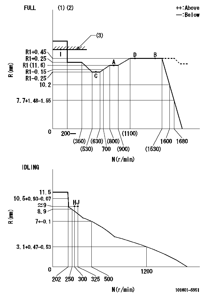
R:Rack position (mm)
(1)Torque cam stamping: T1
(2)Tolerance for racks not indicated: +-0.05mm.
(3)RACK LIMIT
----------
T1=H15
----------
----------
T1=H15
----------
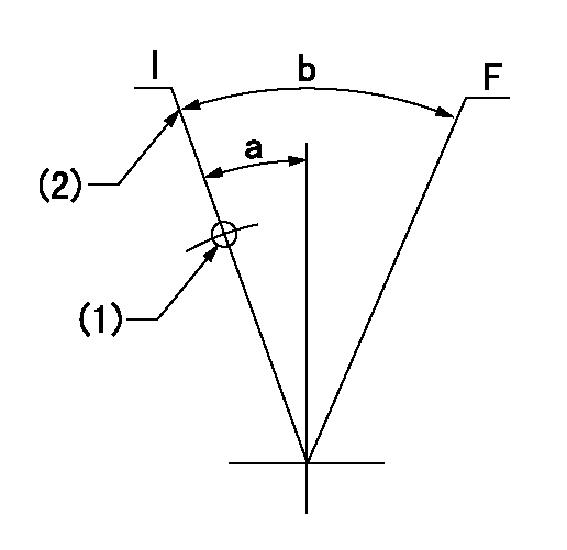
Speed control lever angle

F:Full speed
I:Idle
(1)Use the hole at R = aa
(2)Stopper bolt set position 'H'
----------
aa=25.5mm
----------
a=12deg+-5deg b=(37deg)+-3deg
----------
aa=25.5mm
----------
a=12deg+-5deg b=(37deg)+-3deg
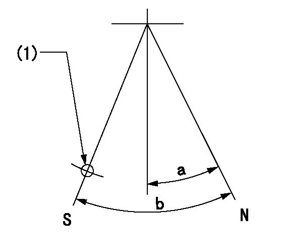
Stop lever angle

N:Pump normal
S:Stop the pump.
(1)Use the hole at R = aa
----------
aa=35mm
----------
a=14.5deg+-5deg b=40deg+-5deg
----------
aa=35mm
----------
a=14.5deg+-5deg b=40deg+-5deg
Timing setting

(1)Pump vertical direction
(2)Coupling's key groove position at No 1 cylinder's beginning of injection
(3)-
(4)-
----------
----------
a=(50deg)
----------
----------
a=(50deg)
Information:
Downhill
When cresting a hill, the decision of whether to use power or not on the downside of the hill must be made. Best fuel economy results from using minimum power to get back to speed after climbing a grade. However, care must be taken not to allow the engine to overspeed. This engine should not exceed 2300 rpm.If equipped with an exhaust brake, the engine should not exceed maximum braking rpm. Refer to "Auxilliary Exhaust Brakes" section of this manual.Saving Fuel On Hills
Rolling hills provide a great opportunity to reduce fuel. Avoid downshifting on small hills. If a hill can be topped without downshifting, even if the engine lugs to the peak torque rpm (1100-1200), the truck should not be downshifted.On long grades that require one or more downshifts, let the engine lug back to the peak torque rpm. If road speed stabilizes with the engine running at or above peak torque rpm, remain in that gear. When going down hill, use gravity instead of engine power to regain vehicle speed.Long steep down grades should be anticipated. Vehicle speed should be reduced before cresting the top of a hill and proceeding down a long steep grade. The way to achieve maximum fuel efficiency, is to minimize the amount of braking that is used to maintain a safe vehicle speed.The engine's ability to hold the truck back increases with engine speed. A gear should be selected that runs the engine near the high engine rpm limit for long steep hills when braking is required.Speed reductions and future stops should be anticipated ahead of time to save fuel. Downshifts should be avoided and the amount of braking minimize