Information injection-pump assembly
BOSCH
F 019 Z10 592
f019z10592
ZEXEL
101601-5900
1016015900
HINO
220007501A
220007501a

Rating:
Service parts 101601-5900 INJECTION-PUMP ASSEMBLY:
1.
_
7.
COUPLING PLATE
8.
_
9.
_
11.
Nozzle and Holder
236002373A
12.
Open Pre:MPa(Kqf/cm2)
19.6(200)
15.
NOZZLE SET
Include in #1:
101601-5900
as INJECTION-PUMP ASSEMBLY
Include in #2:
104137-4003
as _
Cross reference number
BOSCH
F 019 Z10 592
f019z10592
ZEXEL
101601-5900
1016015900
HINO
220007501A
220007501a
Zexel num
Bosch num
Firm num
Name
Calibration Data:
Adjustment conditions
Test oil
1404 Test oil ISO4113 or {SAEJ967d}
1404 Test oil ISO4113 or {SAEJ967d}
Test oil temperature
degC
40
40
45
Nozzle and nozzle holder
105780-8140
Bosch type code
EF8511/9A
Nozzle
105780-0000
Bosch type code
DN12SD12T
Nozzle holder
105780-2080
Bosch type code
EF8511/9
Opening pressure
MPa
17.2
Opening pressure
kgf/cm2
175
Injection pipe
Outer diameter - inner diameter - length (mm) mm 6-2-600
Outer diameter - inner diameter - length (mm) mm 6-2-600
Overflow valve
131424-8320
Overflow valve opening pressure
kPa
108
88
128
Overflow valve opening pressure
kgf/cm2
1.1
0.9
1.3
Tester oil delivery pressure
kPa
157
157
157
Tester oil delivery pressure
kgf/cm2
1.6
1.6
1.6
Direction of rotation (viewed from drive side)
Left L
Left L
Injection timing adjustment
Direction of rotation (viewed from drive side)
Left L
Left L
Injection order
1-4-2-6-
3-5
Pre-stroke
mm
4.3
4.27
4.33
Beginning of injection position
Governor side NO.1
Governor side NO.1
Difference between angles 1
Cal 1-4 deg. 60 59.75 60.25
Cal 1-4 deg. 60 59.75 60.25
Difference between angles 2
Cyl.1-2 deg. 120 119.75 120.25
Cyl.1-2 deg. 120 119.75 120.25
Difference between angles 3
Cal 1-6 deg. 180 179.75 180.25
Cal 1-6 deg. 180 179.75 180.25
Difference between angles 4
Cal 1-3 deg. 240 239.75 240.25
Cal 1-3 deg. 240 239.75 240.25
Difference between angles 5
Cal 1-5 deg. 300 299.75 300.25
Cal 1-5 deg. 300 299.75 300.25
Injection quantity adjustment
Adjusting point
-
Rack position
12.7
Pump speed
r/min
900
900
900
Average injection quantity
mm3/st.
90.3
88.7
91.9
Max. variation between cylinders
%
0
-3.5
3.5
Basic
*
Fixing the rack
*
Standard for adjustment of the maximum variation between cylinders
*
Injection quantity adjustment_02
Adjusting point
H
Rack position
9.5+-0.5
Pump speed
r/min
250
250
250
Each cylinder's injection qty
mm3/st.
15.4
14.4
16.4
Fixing the rack
*
Standard for adjustment of the maximum variation between cylinders
*
Injection quantity adjustment_03
Adjusting point
A
Rack position
R1(12.7)
Pump speed
r/min
900
900
900
Average injection quantity
mm3/st.
90.3
89.3
91.3
Basic
*
Fixing the lever
*
Injection quantity adjustment_04
Adjusting point
B
Rack position
R1+0.55
Pump speed
r/min
1450
1450
1450
Average injection quantity
mm3/st.
93.7
89.7
97.7
Fixing the lever
*
Injection quantity adjustment_05
Adjusting point
C
Rack position
R1-0.7
Pump speed
r/min
600
600
600
Average injection quantity
mm3/st.
75.7
71.7
79.7
Fixing the lever
*
Injection quantity adjustment_06
Adjusting point
I
Rack position
-
Pump speed
r/min
100
100
100
Average injection quantity
mm3/st.
136
136
146
Fixing the lever
*
Rack limit
*
Timer adjustment
Pump speed
r/min
950--
Advance angle
deg.
0
0
0
Load
1/4
Remarks
Start
Start
Timer adjustment_02
Pump speed
r/min
900
Advance angle
deg.
0.3
Load
1/4
Timer adjustment_03
Pump speed
r/min
(1000)
Advance angle
deg.
1.5
1.2
1.8
Load
4/4
Remarks
Measure the actual speed.
Measure the actual speed.
Timer adjustment_04
Pump speed
r/min
1210+50
Advance angle
deg.
1.5
1.2
1.8
Load
3/4
Timer adjustment_05
Pump speed
r/min
1450-50
Advance angle
deg.
5
4.7
5.3
Load
4/4
Remarks
Finish
Finish
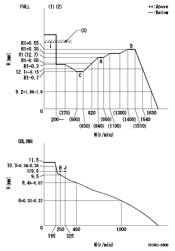
Test data Ex:
Governor adjustment

N:Pump speed
R:Rack position (mm)
(1)Torque cam stamping: T1
(2)Tolerance for racks not indicated: +-0.05mm.
(3)RACK LIMIT
----------
T1=G65
----------
----------
T1=G65
----------
Speed control lever angle

F:Full speed
I:Idle
(1)Use the hole at R = aa
(2)Stopper bolt set position 'H'
----------
aa=46mm
----------
a=34deg+-5deg b=(38deg)+-3deg
----------
aa=46mm
----------
a=34deg+-5deg b=(38deg)+-3deg
Stop lever angle

N:Pump normal
S:Stop the pump.
----------
----------
a=28deg+-5deg b=40deg+-5deg
----------
----------
a=28deg+-5deg b=40deg+-5deg
Timing setting

(1)Pump vertical direction
(2)Coupling's key groove position at No 1 cylinder's beginning of injection
(3)-
(4)-
----------
----------
a=(20deg)
----------
----------
a=(20deg)
Information:
3. Shake the core vigorously to eliminate any trapped debris.4. Wash the core with hot, soapy water. Rinse thoroughly with clean water.5. Dry the core with compressed air. Blow air in reverse direction of normal flow. Use all necessary safety equipment while using compressed air.6. Inspect the system to ensure cleanliness and install the core.Coolant Analysis
Obtain
There are two types of coolant analysis that can be performed. First, the concentration of supplemental coolant additives (conditioner) should be checked regularly for over or under concentration. The intervals recommended for re-charging with supplemental coolant additive should be adequate for many users, but it is a good idea to periodically check the concentration.For checking the concentration of coolant conditioner, Caterpillar offers an 8T5296 test kit.At overhaul time, a further coolant analysis may be desirable. For example, suppose considerable deposits are found in the water jacket areas on the external cooling system, yet supplemental coolant additive concentrations were carefully maintained. Chances are that the coolant water had minerals which deposited on the engine over time. One way to verify the water condition, or to be sure of new water at fill time, is to have a water analysis conducted.Full water analysis can sometimes be obtained locally by contacting your local water utility company or an agricultural agent. Private laboratories are also available. Many Caterpillar dealers and customers send water samples to:L.O.C.C. Corporation
905 Bayshore Drive
Coos Bay, Oregon 97420 U.S.A.
Telephone: (503) 267-4904
NALCO Chemical Co.
Naperville Technical Center
One Nalco Center
Naperville, IL 60566
Attn: Sample Receiving
Ph. (312) 961-9500
To analyze a water sample, most laboratories need approximately 250 ml (1/2 pint) of water. Check the lab you use for details about labeling and shipping.After Failure Overhaul
If you experience a major engine failure which requires removal of the engine, there are also many After Failure Overhaul options available. An overhaul should be performed if your block or crankshaft needs to be repaired.If the block and/or crankshaft is repairable, then the cost of an overhaul should be between 40 and 50 percent of the cost of a new engine (with like exchange core).This lower cost can be attributed to Caterpillar "designed-in" features that include:* Regrindable crankshaft* Undersize bearings, if needed* Cat dealer and Caterpillar Remanufactured exchange components Dealer Exchange Components - This cost cutting service permits you to exchange worn engine components for quality Caterpillar dealer rebuilt components on an over-the-counter basis. When you need them, these parts are ready for a substantial savings in both time and money. Caterpillar Remanufactured Components - Manufacturing techniques and processes are used to restore your components to "like-new" performance capabilities and are exchanged for your existing parts. The processes used result in an end product that conforms to Caterpillar's original functional specifications.The following is a list of (R) Remanufactured components that can be found in the Parts Book and currently being offered by Caterpillar* in many countries:* Short block* Cylinder pack1* Cylinder head - bare casting* Cylinder head - assembled* Crankshaft - undersized*** Crankshaft - upgrade to new* Complete turbocharger* Turbocharger Piece Parts* Turbocharger Cartridges*