Information injection-pump assembly
ZEXEL
101601-5883
1016015883
HINO
220203882A
220203882a

Rating:
Service parts 101601-5883 INJECTION-PUMP ASSEMBLY:
1.
_
6.
COUPLING PLATE
7.
COUPLING PLATE
8.
_
9.
_
11.
Nozzle and Holder
23600-2150
12.
Open Pre:MPa(Kqf/cm2)
21.6{220}
15.
NOZZLE SET
Include in #1:
101601-5883
as INJECTION-PUMP ASSEMBLY
Include in #2:
104137-4000
as _
Cross reference number
ZEXEL
101601-5883
1016015883
HINO
220203882A
220203882a
Zexel num
Bosch num
Firm num
Name
Calibration Data:
Adjustment conditions
Test oil
1404 Test oil ISO4113 or {SAEJ967d}
1404 Test oil ISO4113 or {SAEJ967d}
Test oil temperature
degC
40
40
45
Nozzle and nozzle holder
105780-8140
Bosch type code
EF8511/9A
Nozzle
105780-0000
Bosch type code
DN12SD12T
Nozzle holder
105780-2080
Bosch type code
EF8511/9
Opening pressure
MPa
17.2
Opening pressure
kgf/cm2
175
Injection pipe
Outer diameter - inner diameter - length (mm) mm 6-2-600
Outer diameter - inner diameter - length (mm) mm 6-2-600
Overflow valve
131424-6420
Overflow valve opening pressure
kPa
255
221
289
Overflow valve opening pressure
kgf/cm2
2.6
2.25
2.95
Tester oil delivery pressure
kPa
157
157
157
Tester oil delivery pressure
kgf/cm2
1.6
1.6
1.6
Direction of rotation (viewed from drive side)
Right R
Right R
Injection timing adjustment
Direction of rotation (viewed from drive side)
Right R
Right R
Injection order
1-4-2-6-
3-5
Pre-stroke
mm
4.4
4.35
4.45
Beginning of injection position
Drive side NO.1
Drive side NO.1
Difference between angles 1
Cal 1-4 deg. 60 59.5 60.5
Cal 1-4 deg. 60 59.5 60.5
Difference between angles 2
Cyl.1-2 deg. 120 119.5 120.5
Cyl.1-2 deg. 120 119.5 120.5
Difference between angles 3
Cal 1-6 deg. 180 179.5 180.5
Cal 1-6 deg. 180 179.5 180.5
Difference between angles 4
Cal 1-3 deg. 240 239.5 240.5
Cal 1-3 deg. 240 239.5 240.5
Difference between angles 5
Cal 1-5 deg. 300 299.5 300.5
Cal 1-5 deg. 300 299.5 300.5
Injection quantity adjustment
Adjusting point
A
Rack position
12.3
Pump speed
r/min
1500
1500
1500
Average injection quantity
mm3/st.
139.5
137.5
141.5
Max. variation between cylinders
%
0
-3
3
Basic
*
Fixing the lever
*
Boost pressure
kPa
70.6
70.6
Boost pressure
mmHg
530
530
Injection quantity adjustment_02
Adjusting point
B
Rack position
7.1+-0.5
Pump speed
r/min
250
250
250
Average injection quantity
mm3/st.
14.5
13
16
Max. variation between cylinders
%
0
-15
15
Fixing the rack
*
Boost pressure
kPa
0
0
0
Boost pressure
mmHg
0
0
0
Boost compensator adjustment
Pump speed
r/min
600
600
600
Rack position
10.4
Boost pressure
kPa
20
17.3
22.7
Boost pressure
mmHg
150
130
170
Boost compensator adjustment_02
Pump speed
r/min
600
600
600
Rack position
12.8
Boost pressure
kPa
57.3
50.6
64
Boost pressure
mmHg
430
380
480
Timer adjustment
Pump speed
r/min
(N1+50)-
-
Advance angle
deg.
0
0
0
Remarks
Start
Start
Timer adjustment_02
Pump speed
r/min
N1
Advance angle
deg.
0.3
Remarks
Measure the actual speed.
Measure the actual speed.
Timer adjustment_03
Pump speed
r/min
-
Advance angle
deg.
1.5
1.2
1.8
Remarks
Measure the actual speed, stop
Measure the actual speed, stop
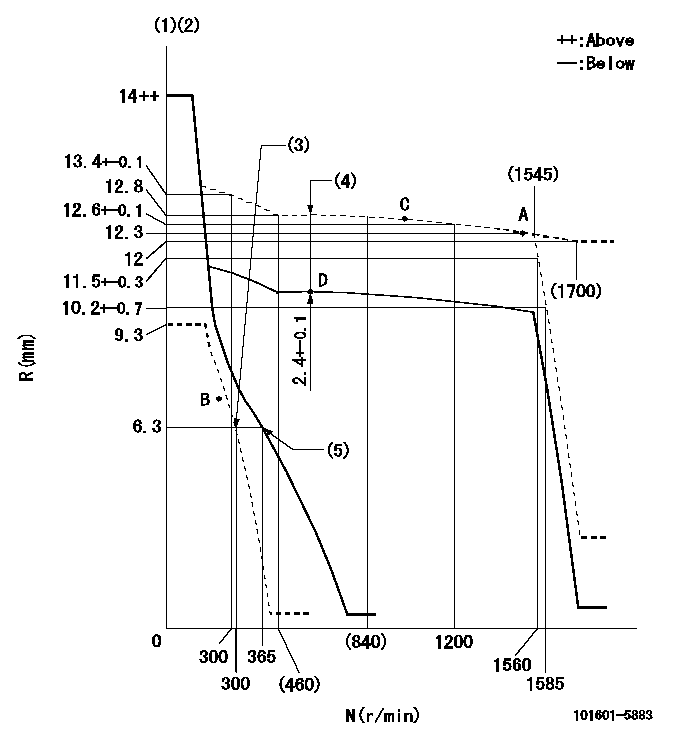
Test data Ex:
Governor adjustment

N:Pump speed
R:Rack position (mm)
(1)Target notch: K
(2)Tolerance for racks not indicated: +-0.05mm.
(3)Set idle sub-spring
(4)Boost compensator stroke
(5)Main spring setting
----------
K=12
----------
----------
K=12
----------
Speed control lever angle

F:Full speed
I:Idle
(1)Stopper bolt setting
----------
----------
a=13deg+-5deg b=30deg+-5deg
----------
----------
a=13deg+-5deg b=30deg+-5deg
Stop lever angle

N:Pump normal
S:Stop the pump.
(1)Pump speed aa and rack position bb (to be sealed at delivery)
----------
aa=0r/min bb=1-0.2mm
----------
a=21deg+-5deg b=(55deg)
----------
aa=0r/min bb=1-0.2mm
----------
a=21deg+-5deg b=(55deg)
Timing setting

(1)Pump vertical direction
(2)Position of gear's standard threaded hole at No 1 cylinder's beginning of injection
(3)-
(4)-
----------
----------
a=(70deg)
----------
----------
a=(70deg)
Information:
Add Coolant Additive (Conditioner)
1. Release the cooling system relief valve slowly to relieve pressure and remove filler cap. Inspect condition of cap gasket. Replace cap if necessary.2. It may be necessary to drain enough coolant from the system to allow for the addition of cooling system additive (conditioner).3. Add Caterpillar Cooling System Conditioner. Add 0.24 liter (1/2 U.S. pint) of Caterpillar Cooling System Additive (Conditioner) for each 38 liter (10 U.S. gallon) of cooling system capacity. This will maintain the required concentration of conditioner. On new, rebuilt or remanufactured engines only, or when draining and changing the coolant, add liquid additive concentration of coolant additive of 1 liter (1 U.S. quart) for every 15 liter (4 U.S. gallon) of cooling system capacity for systems using water as coolant only.Caterpillar Antifreeze contains the necessary coolant additive precharge. Only add the coolant additive precharge if you have decided not to use Caterpillar Antifreeze.Refer to the Refill Capacities chart in this publication for the cooling system capacity for your engine.
Do not use any Methoxypropanol-based antifreeze or coolants such as Dowtherm 209 Full-Fill coolant in the cooling system. Methoxypropanol will cause some seals and gaskets to deteriorate and fail.
4. Maintain coolant level to within 13 mm (1/2 in) below the bottom of the filler tube or to the proper level (upper half) on the sight glass, if equipped. Add premixed coolant if necessary to bring the coolant to the proper level.Refer to the topic Cooling System Specifications in the Specifications section in this manual for additional information about coolant mixture and supplemental coolant additive.5. Start the engine and check for leaks or damaged piping. Allow the coolant level to stabilize. Inspect the cooling system pipes and lines for leaks and/or damaged connections. Make repairs if necessary. Install the filler cap.Coolant Analysis
Obtain Coolant Sample
There are