Information injection-pump assembly
BOSCH
9 400 614 631
9400614631
ZEXEL
101601-5821
1016015821
HINO
220007460A
220007460a

Rating:
Service parts 101601-5821 INJECTION-PUMP ASSEMBLY:
1.
_
6.
COUPLING PLATE
7.
COUPLING PLATE
8.
_
9.
_
11.
Nozzle and Holder
12.
Open Pre:MPa(Kqf/cm2)
19.6(220)
15.
NOZZLE SET
Cross reference number
BOSCH
9 400 614 631
9400614631
ZEXEL
101601-5821
1016015821
HINO
220007460A
220007460a
Zexel num
Bosch num
Firm num
Name
101601-5821
9 400 614 631
220007460A HINO
INJECTION-PUMP ASSEMBLY
W06E * K
W06E * K
Calibration Data:
Adjustment conditions
Test oil
1404 Test oil ISO4113 or {SAEJ967d}
1404 Test oil ISO4113 or {SAEJ967d}
Test oil temperature
degC
40
40
45
Nozzle and nozzle holder
105780-8140
Bosch type code
EF8511/9A
Nozzle
105780-0000
Bosch type code
DN12SD12T
Nozzle holder
105780-2080
Bosch type code
EF8511/9
Opening pressure
MPa
17.2
Opening pressure
kgf/cm2
175
Injection pipe
Outer diameter - inner diameter - length (mm) mm 6-2-600
Outer diameter - inner diameter - length (mm) mm 6-2-600
Overflow valve
131424-5720
Overflow valve opening pressure
kPa
255
221
289
Overflow valve opening pressure
kgf/cm2
2.6
2.25
2.95
Tester oil delivery pressure
kPa
157
157
157
Tester oil delivery pressure
kgf/cm2
1.6
1.6
1.6
Direction of rotation (viewed from drive side)
Right R
Right R
Injection timing adjustment
Direction of rotation (viewed from drive side)
Right R
Right R
Injection order
1-4-2-6-
3-5
Pre-stroke
mm
3.1
3.07
3.13
Beginning of injection position
Drive side NO.1
Drive side NO.1
Difference between angles 1
Cal 1-4 deg. 60 59.75 60.25
Cal 1-4 deg. 60 59.75 60.25
Difference between angles 2
Cyl.1-2 deg. 120 119.75 120.25
Cyl.1-2 deg. 120 119.75 120.25
Difference between angles 3
Cal 1-6 deg. 180 179.75 180.25
Cal 1-6 deg. 180 179.75 180.25
Difference between angles 4
Cal 1-3 deg. 240 239.75 240.25
Cal 1-3 deg. 240 239.75 240.25
Difference between angles 5
Cal 1-5 deg. 300 299.75 300.25
Cal 1-5 deg. 300 299.75 300.25
Injection quantity adjustment
Adjusting point
-
Rack position
9.4
Pump speed
r/min
900
900
900
Average injection quantity
mm3/st.
58.5
56.5
60.5
Max. variation between cylinders
%
0
-3.5
3.5
Basic
*
Fixing the rack
*
Standard for adjustment of the maximum variation between cylinders
*
Injection quantity adjustment_02
Adjusting point
H
Rack position
8+-0.5
Pump speed
r/min
250
250
250
Average injection quantity
mm3/st.
6.8
5.3
8.3
Max. variation between cylinders
%
0
-10
10
Fixing the rack
*
Standard for adjustment of the maximum variation between cylinders
*
Injection quantity adjustment_03
Adjusting point
A
Rack position
R1(9.4)
Pump speed
r/min
900
900
900
Average injection quantity
mm3/st.
58.5
57.5
59.5
Basic
*
Fixing the lever
*
Injection quantity adjustment_04
Adjusting point
B
Rack position
R1+0.2
Pump speed
r/min
1500
1500
1500
Average injection quantity
mm3/st.
67.3
63.3
71.3
Fixing the lever
*
Injection quantity adjustment_05
Adjusting point
C
Rack position
R1-0.35
Pump speed
r/min
600
600
600
Average injection quantity
mm3/st.
37.9
33.9
41.9
Fixing the lever
*
Injection quantity adjustment_06
Adjusting point
D
Rack position
R1+0.25
Pump speed
r/min
1200
1200
1200
Average injection quantity
mm3/st.
67.8
63.8
71.8
Fixing the lever
*
Injection quantity adjustment_07
Adjusting point
E
Rack position
R1+0.1
Pump speed
r/min
400
400
400
Average injection quantity
mm3/st.
32.9
28.9
36.9
Fixing the lever
*
Injection quantity adjustment_08
Adjusting point
I
Rack position
-
Pump speed
r/min
100
100
100
Average injection quantity
mm3/st.
99
99
109
Fixing the lever
*
Rack limit
*
Timer adjustment
Pump speed
r/min
1000+50
Advance angle
deg.
0
0
0
Remarks
Start
Start
Timer adjustment_02
Pump speed
r/min
1500
Advance angle
deg.
3.5
3.2
3.8
Remarks
Finish
Finish
Test data Ex:
Governor adjustment
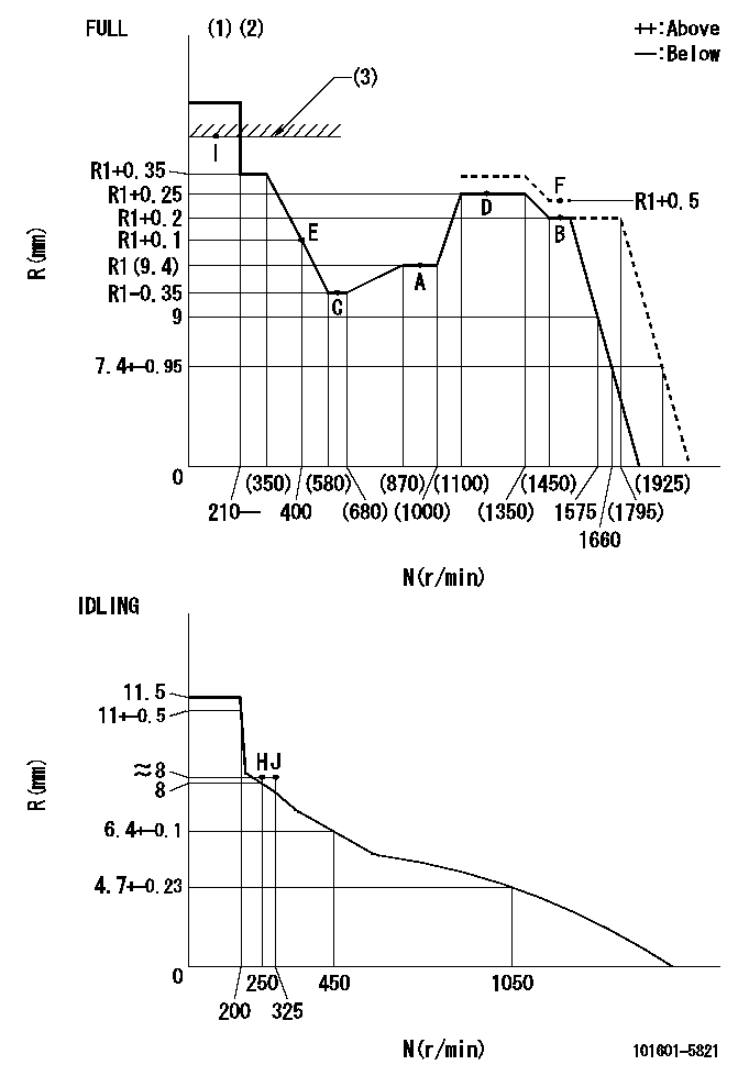
N:Pump speed
R:Rack position (mm)
(1)Torque cam stamping: T1
(2)Tolerance for racks not indicated: +-0.05mm.
(3)RACK LIMIT
----------
T1=F94
----------
----------
T1=F94
----------
Speed control lever angle

F:Full speed
I:Idle
(1)Stopper bolt set position 'H'
----------
----------
a=32deg+-3deg b=34deg+-5deg
----------
----------
a=32deg+-3deg b=34deg+-5deg
Stop lever angle
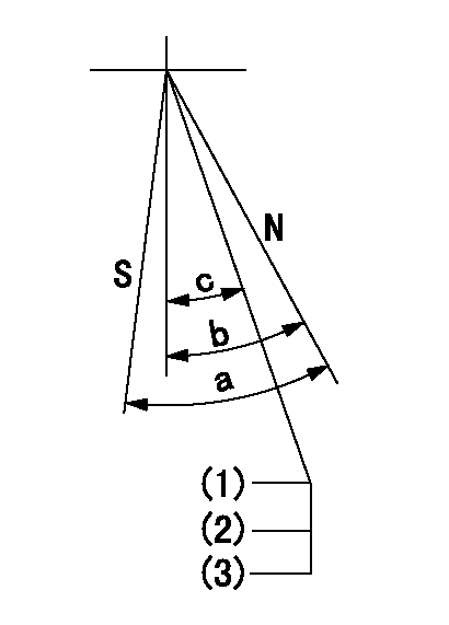
N:Pump normal
S:Stop the pump.
(1)Stopper bolt setting
(2)(Apply red paint after setting.)
(3)Engine normal
----------
----------
a=40deg+-5deg b=40deg+-5deg c=35deg+-2deg
----------
----------
a=40deg+-5deg b=40deg+-5deg c=35deg+-2deg
0000001501 TAMPER PROOF
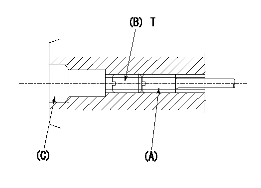
1. Method for setting tamperproof proofing
(1)After governor adjustment (torque cam phase adjustment), move the load lever to increase the full rack position to Ra.
(2)At pump speed N1, push in the screw (A) until the rack position is Rb.
(3)Temporarily caulk using the tip of a screwdriver
(4)Confirm that the rack at that time is at Rc.
(5)Lock using setscrew (B). (Tightening torque = T)
(6)Next, coat (C) with adhesive and then pressfit.
(7)Then, readjust the full rack position using the load lever.
----------
N1=1500r/min Ra=(0.4)mm Rb=R1(9.4)+0.5mm Rc=R1(9.4)+0.5mm
----------
T=4.9~7N-m(0.5~0.7Kgf-m)
----------
N1=1500r/min Ra=(0.4)mm Rb=R1(9.4)+0.5mm Rc=R1(9.4)+0.5mm
----------
T=4.9~7N-m(0.5~0.7Kgf-m)
Timing setting

(1)Pump vertical direction
(2)Position of gear's standard threaded hole at No 1 cylinder's beginning of injection
(3)-
(4)-
----------
----------
a=(70deg)
----------
----------
a=(70deg)
Information:
Use Caterpillar Antifreeze or any low silicate (ethylene or propylene glycol) antifreeze that meets ASTM D4985 requirements. Most commercial antifreezes are formulated for gasoline engine applications and have high silicate content. Caterpillar Antifreeze is formulated with a low silicate content and the proper coolant additives for heavy duty diesel engines.Caterpillar Antifreeze is available through your Caterpillar dealer in quantities that follow. Adding pure undiluted antifreeze as a makeup solution for cooling system top-off is an unacceptable practice. Add antifreeze premixed with acceptable water to the same freeze protection as your cooling system. Use the Antifreeze Concentration chart to assist in determining the concentration of Caterpillar Antifreeze to use. Check the coolant solution frequently in cold weather for glycol concentration with the 5P0957 or 5P3514 Coolant Tester (for Caterpillar products) to ensure adequate freeze protection. The testers are identical except temperature scales (°C or °F) and give immediate accurate readings for antifreeze/coolants that contain ethylene or propylene glycol. Both testers are available at your Caterpillar dealer.
If propylene glycol based antifreeze is used, DO NOT allow concentration greater than a 60/40 antifreeze to water mixture. The measurement of freeze protection must be made with a refractive-type tester (5P0957 or 5P3514) rather than the hydrometer-type tester commercially available. The hydrometer-type tester can be used to test ethylene glycol based antifreeze.
Supplemental Coolant Additive (Conditioner or Inhibitor)
The cooling system MUST contain supplemental coolant additives (conditioner or inhibitor) to control corrosion, cavitation and deposits. It is also necessary to prevent rust, scale, pitting and/or corrosion of engine parts contacted by coolant. The cooling system should be protected with a minimum of three percent concentration at all times, regardless of the concentration of antifreeze. Use supplemental coolant additive liquid OR an element (if equipped) to maintain a three to six percent concentration in the cooling system. Supplemental Coolant Additive must be used with propylene glycol or ethylene glycol antifreeze at the same concentration.
Never use antifreeze/water coolant only, in Caterpillar engines without supplemental coolant additive regardless of antifreeze concentration.Caterpillar or other manufacturer's products can be used as the supplemental coolant additive. DO NOT mix Caterpillar Supplemental Coolant Additive (Conditioner) liquid or elements with the other commercial products available; select a cooling system treatment and use it exclusively.Excessive concentration of supplemental coolant additive can form deposits which may cause engine damage, reduce the engine's heat transfer characteristics and could also accelerate water pump seal wear.
Use the 8T5296 Test Kit to check and monitor the SCA concentration for antifreeze/water coolant mixture. The Caterpillar 8T5296 Test Kit checks for concentration of nitrates in the coolant solution. Some other manufacturers' supplemental coolant additive (SCA) are phosphate based and the 8T5296 Test Kit will NOT provide accurate results. Caterpillar recommends that their test kit be used to check coolant solution concentration.If other than Caterpillar products are used as the supplemental coolant additive, follow the manufacturers' recommendation for cooling system treatment and test evaluation. Commercial supplemental coolant additive products must contain silicates and a minimum of 70 gr/U.S. gallon (1200 ppm)
Have questions with 101601-5821?
Group cross 101601-5821 ZEXEL
Hino
Hino
Hino
101601-5821
9 400 614 631
220007460A
INJECTION-PUMP ASSEMBLY
W06E
W06E