Information injection-pump assembly
ZEXEL
101601-5820
1016015820
Rating:
Service parts 101601-5820 INJECTION-PUMP ASSEMBLY:
1.
_
6.
COUPLING PLATE
7.
COUPLING PLATE
8.
_
9.
_
11.
Nozzle and Holder
23600-1593A
12.
Open Pre:MPa(Kqf/cm2)
21.6{220}
15.
NOZZLE SET
Cross reference number
ZEXEL
101601-5820
1016015820
Zexel num
Bosch num
Firm num
Name
101601-5820
INJECTION-PUMP ASSEMBLY
Calibration Data:
Adjustment conditions
Test oil
1404 Test oil ISO4113 or {SAEJ967d}
1404 Test oil ISO4113 or {SAEJ967d}
Test oil temperature
degC
40
40
45
Nozzle and nozzle holder
105780-8140
Bosch type code
EF8511/9A
Nozzle
105780-0000
Bosch type code
DN12SD12T
Nozzle holder
105780-2080
Bosch type code
EF8511/9
Opening pressure
MPa
17.2
Opening pressure
kgf/cm2
175
Injection pipe
Outer diameter - inner diameter - length (mm) mm 6-2-600
Outer diameter - inner diameter - length (mm) mm 6-2-600
Overflow valve
131424-5720
Overflow valve opening pressure
kPa
255
221
289
Overflow valve opening pressure
kgf/cm2
2.6
2.25
2.95
Tester oil delivery pressure
kPa
157
157
157
Tester oil delivery pressure
kgf/cm2
1.6
1.6
1.6
Direction of rotation (viewed from drive side)
Right R
Right R
Injection timing adjustment
Direction of rotation (viewed from drive side)
Right R
Right R
Injection order
1-4-2-6-
3-5
Pre-stroke
mm
3.1
3.07
3.13
Beginning of injection position
Drive side NO.1
Drive side NO.1
Difference between angles 1
Cal 1-4 deg. 60 59.75 60.25
Cal 1-4 deg. 60 59.75 60.25
Difference between angles 2
Cyl.1-2 deg. 120 119.75 120.25
Cyl.1-2 deg. 120 119.75 120.25
Difference between angles 3
Cal 1-6 deg. 180 179.75 180.25
Cal 1-6 deg. 180 179.75 180.25
Difference between angles 4
Cal 1-3 deg. 240 239.75 240.25
Cal 1-3 deg. 240 239.75 240.25
Difference between angles 5
Cal 1-5 deg. 300 299.75 300.25
Cal 1-5 deg. 300 299.75 300.25
Injection quantity adjustment
Adjusting point
-
Rack position
9.4
Pump speed
r/min
900
900
900
Average injection quantity
mm3/st.
58.5
56.5
60.5
Max. variation between cylinders
%
0
-3.5
3.5
Basic
*
Fixing the rack
*
Standard for adjustment of the maximum variation between cylinders
*
Injection quantity adjustment_02
Adjusting point
H
Rack position
8+-0.5
Pump speed
r/min
250
250
250
Average injection quantity
mm3/st.
6.8
5.3
8.3
Max. variation between cylinders
%
0
-10
10
Fixing the rack
*
Standard for adjustment of the maximum variation between cylinders
*
Injection quantity adjustment_03
Adjusting point
A
Rack position
R1(9.4)
Pump speed
r/min
900
900
900
Average injection quantity
mm3/st.
58.5
57.5
59.5
Basic
*
Fixing the lever
*
Injection quantity adjustment_04
Adjusting point
B
Rack position
R1+0.2
Pump speed
r/min
1500
1500
1500
Average injection quantity
mm3/st.
67.3
63.3
71.3
Fixing the lever
*
Injection quantity adjustment_05
Adjusting point
C
Rack position
R1-0.35
Pump speed
r/min
600
600
600
Average injection quantity
mm3/st.
37.9
33.9
41.9
Fixing the lever
*
Injection quantity adjustment_06
Adjusting point
D
Rack position
R1+0.25
Pump speed
r/min
1200
1200
1200
Average injection quantity
mm3/st.
67.8
63.8
71.8
Fixing the lever
*
Injection quantity adjustment_07
Adjusting point
E
Rack position
R1+0.1
Pump speed
r/min
400
400
400
Average injection quantity
mm3/st.
32.9
28.9
36.9
Fixing the lever
*
Injection quantity adjustment_08
Adjusting point
I
Rack position
-
Pump speed
r/min
100
100
100
Average injection quantity
mm3/st.
99
99
109
Fixing the lever
*
Rack limit
*
Timer adjustment
Pump speed
r/min
1000+50
Advance angle
deg.
0
0
0
Remarks
Start
Start
Timer adjustment_02
Pump speed
r/min
1500
Advance angle
deg.
3.5
3.2
3.8
Remarks
Finish
Finish
Test data Ex:
Governor adjustment
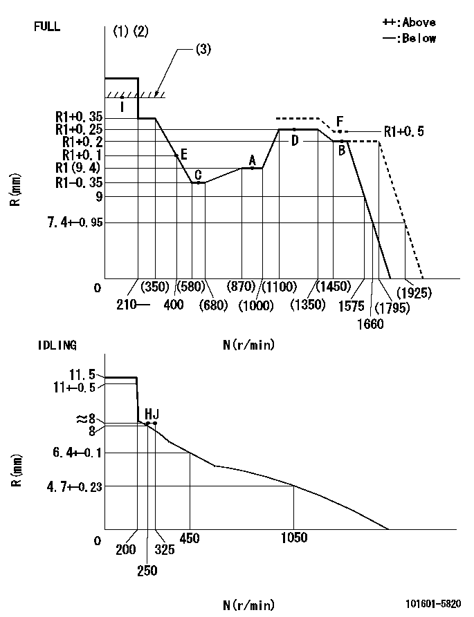
N:Pump speed
R:Rack position (mm)
(1)Torque cam stamping: T1
(2)Tolerance for racks not indicated: +-0.05mm.
(3)RACK LIMIT
----------
T1=F94
----------
----------
T1=F94
----------
Speed control lever angle

F:Full speed
I:Idle
(1)Stopper bolt set position 'H'
----------
----------
a=32deg+-3deg b=34deg+-5deg
----------
----------
a=32deg+-3deg b=34deg+-5deg
Stop lever angle
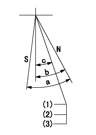
N:Pump normal
S:Stop the pump.
(1)Stopper bolt setting
(2)(Apply red paint after setting.)
(3)Engine normal
----------
----------
a=40deg+-5deg b=40deg+-5deg c=35deg+-2deg
----------
----------
a=40deg+-5deg b=40deg+-5deg c=35deg+-2deg
0000001501 TAMPER PROOF
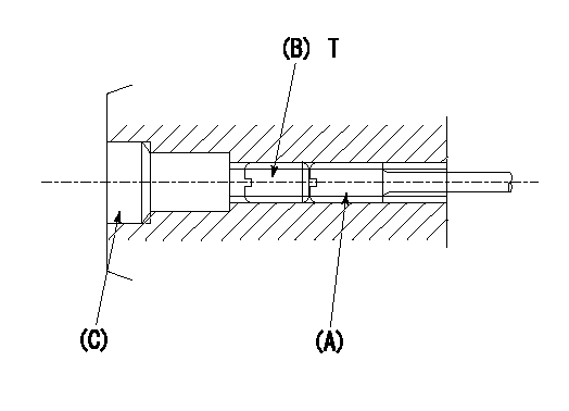
1. Method for setting tamperproof proofing
(1)After governor adjustment (torque cam phase adjustment), move the load lever to increase the full rack position to Ra.
(2)At pump speed N1, push in the screw (A) until the rack position is Rb.
(3)Temporarily caulk using the tip of a screwdriver
(4)Confirm that the rack at that time is at Rc.
(5)Lock using setscrew (B). (Tightening torque = T)
(6)Next, coat (C) with adhesive and then pressfit.
(7)Then, readjust the full rack position using the load lever.
----------
N1=1500r/min Ra=(0.4)mm Rb=R1(9.4)+0.5mm Rc=R1(9.4)+0.5mm
----------
T=3.4~4.9N-m(0.35~0.5Kgf-m)
----------
N1=1500r/min Ra=(0.4)mm Rb=R1(9.4)+0.5mm Rc=R1(9.4)+0.5mm
----------
T=3.4~4.9N-m(0.35~0.5Kgf-m)
Timing setting

(1)Pump vertical direction
(2)Position of gear's standard threaded hole at No 1 cylinder's beginning of injection
(3)-
(4)-
----------
----------
a=(70deg)
----------
----------
a=(70deg)
Information:
For additional torque specifications, not included in this section, refer to Torque Specifications, SENR3130 available from your Caterpillar dealer.Torque for Standard Fasteners
The following charts give general torques for bolts, nuts and taperlock studs of SAE Grade 5 or better quality.
Torque for Bolts, Nuts and Taperlock Studs
Use these standard torque values for all fasteners unless otherwise specified in this publication or in the Service Manual.Torque for Metric Fasteners
Be very careful never to mix metric with U.S. customary (standard) fasteners. Mismatched or incorrect fasteners will cause engine damage or malfunction and may even result in personal injury.Original fasteners removed from the engine should be saved for reassembly whenever possible. If new fasteners are needed, they must be of the same size and grade as the ones that are being replaced.The material strength identification is usually shown on the bolt head by numbers (8.8, 10.9, etc.). The following chart gives general torques for bolts and nuts with Metric Threads of SAE Grade 8.8 or better quality.
Metric hardware must be replaced with metric hardware. Check parts manual for proper replacement.Torques for Bolts, Nuts and Taperlock Studs with Metric Threads
Torque for Standard Hose Clamps-Worm Drive Band Type
The following chart gives the torques for initial installation of hose clamps on new hose and for reassembly or tightening of hose clamps on existing hose.
Torque for Constant Torque Hose Clamps
A constant torque hose clamp can be used in place of any standard hose clamp. make sure the constant torque hose clamp is the same size as the standard clamp. Due to extreme temperature changes, hose will heat set. Heat setting causes hose clamps to loosen. Loose hose clamps can result in leaks. There have been reports of component failures caused by hose clamps loosening. The new, constant torque hose clamp will help prevent these failures.Each installation application can be different depending on the type of hose, fitting material and anticipated expansion or contraction of the hose and fittings. A torque wrench should be used for proper installation of the new, constant torque hose clamps. Constant torque hose clamps should be installed as follows:* To allow for maximum expansion, install clamps at 5.7 N m (50 lb in).* To allow for equal expansion and contraction, install clamps at 10.2 N m (90 lb in).* To allow for maximum contraction, install clamps at 14.1 N m (125 lb in).
Have questions with 101601-5820?
Group cross 101601-5820 ZEXEL
Hino
Hino
101601-5820
INJECTION-PUMP ASSEMBLY