Information injection-pump assembly
BOSCH
9 400 614 629
9400614629
ZEXEL
101601-5802
1016015802
HINO
220007421A
220007421a

Rating:
Service parts 101601-5802 INJECTION-PUMP ASSEMBLY:
1.
_
6.
COUPLING PLATE
7.
COUPLING PLATE
8.
_
9.
_
11.
Nozzle and Holder
12.
Open Pre:MPa(Kqf/cm2)
19.6(220)
15.
NOZZLE SET
Include in #1:
101601-5802
as INJECTION-PUMP ASSEMBLY
Include in #2:
104207-3002
as _
Cross reference number
BOSCH
9 400 614 629
9400614629
ZEXEL
101601-5802
1016015802
HINO
220007421A
220007421a
Zexel num
Bosch num
Firm num
Name
101601-5802
9 400 614 629
220007421A HINO
INJECTION-PUMP ASSEMBLY
W06D K
W06D K
Calibration Data:
Adjustment conditions
Test oil
1404 Test oil ISO4113 or {SAEJ967d}
1404 Test oil ISO4113 or {SAEJ967d}
Test oil temperature
degC
40
40
45
Nozzle and nozzle holder
105780-8140
Bosch type code
EF8511/9A
Nozzle
105780-0000
Bosch type code
DN12SD12T
Nozzle holder
105780-2080
Bosch type code
EF8511/9
Opening pressure
MPa
17.2
Opening pressure
kgf/cm2
175
Injection pipe
Outer diameter - inner diameter - length (mm) mm 6-2-600
Outer diameter - inner diameter - length (mm) mm 6-2-600
Overflow valve
131424-5720
Overflow valve opening pressure
kPa
255
221
289
Overflow valve opening pressure
kgf/cm2
2.6
2.25
2.95
Tester oil delivery pressure
kPa
157
157
157
Tester oil delivery pressure
kgf/cm2
1.6
1.6
1.6
Direction of rotation (viewed from drive side)
Right R
Right R
Injection timing adjustment
Direction of rotation (viewed from drive side)
Right R
Right R
Injection order
1-4-2-6-
3-5
Pre-stroke
mm
3.1
3.07
3.13
Beginning of injection position
Drive side NO.1
Drive side NO.1
Difference between angles 1
Cal 1-4 deg. 60 59.75 60.25
Cal 1-4 deg. 60 59.75 60.25
Difference between angles 2
Cyl.1-2 deg. 120 119.75 120.25
Cyl.1-2 deg. 120 119.75 120.25
Difference between angles 3
Cal 1-6 deg. 180 179.75 180.25
Cal 1-6 deg. 180 179.75 180.25
Difference between angles 4
Cal 1-3 deg. 240 239.75 240.25
Cal 1-3 deg. 240 239.75 240.25
Difference between angles 5
Cal 1-5 deg. 300 299.75 300.25
Cal 1-5 deg. 300 299.75 300.25
Injection quantity adjustment
Adjusting point
-
Rack position
8.7
Pump speed
r/min
1000
1000
1000
Average injection quantity
mm3/st.
44.4
42.4
46.4
Max. variation between cylinders
%
0
-3.5
3.5
Basic
*
Fixing the rack
*
Standard for adjustment of the maximum variation between cylinders
*
Injection quantity adjustment_02
Adjusting point
H
Rack position
8+-0.5
Pump speed
r/min
250
250
250
Average injection quantity
mm3/st.
8
6.5
9.5
Max. variation between cylinders
%
0
-10
10
Fixing the rack
*
Standard for adjustment of the maximum variation between cylinders
*
Injection quantity adjustment_03
Adjusting point
A
Rack position
R1(8.7)
Pump speed
r/min
1000
1000
1000
Average injection quantity
mm3/st.
44.4
43.4
45.4
Basic
*
Fixing the lever
*
Injection quantity adjustment_04
Adjusting point
B
Rack position
R1-0.3
Pump speed
r/min
1600
1600
1600
Average injection quantity
mm3/st.
43.5
41.5
45.5
Fixing the lever
*
Injection quantity adjustment_05
Adjusting point
C
Rack position
R1-0.1
Pump speed
r/min
1300
1300
1300
Average injection quantity
mm3/st.
44.1
42.1
46.1
Fixing the lever
*
Injection quantity adjustment_06
Adjusting point
D
Rack position
R1-0.2
Pump speed
r/min
650
650
650
Average injection quantity
mm3/st.
36.2
34.2
38.2
Fixing the lever
*
Timer adjustment
Pump speed
r/min
1300+50
Advance angle
deg.
0
0
0
Remarks
Start
Start
Timer adjustment_02
Pump speed
r/min
1600
Advance angle
deg.
5
4.7
5.3
Remarks
Finish
Finish
Test data Ex:
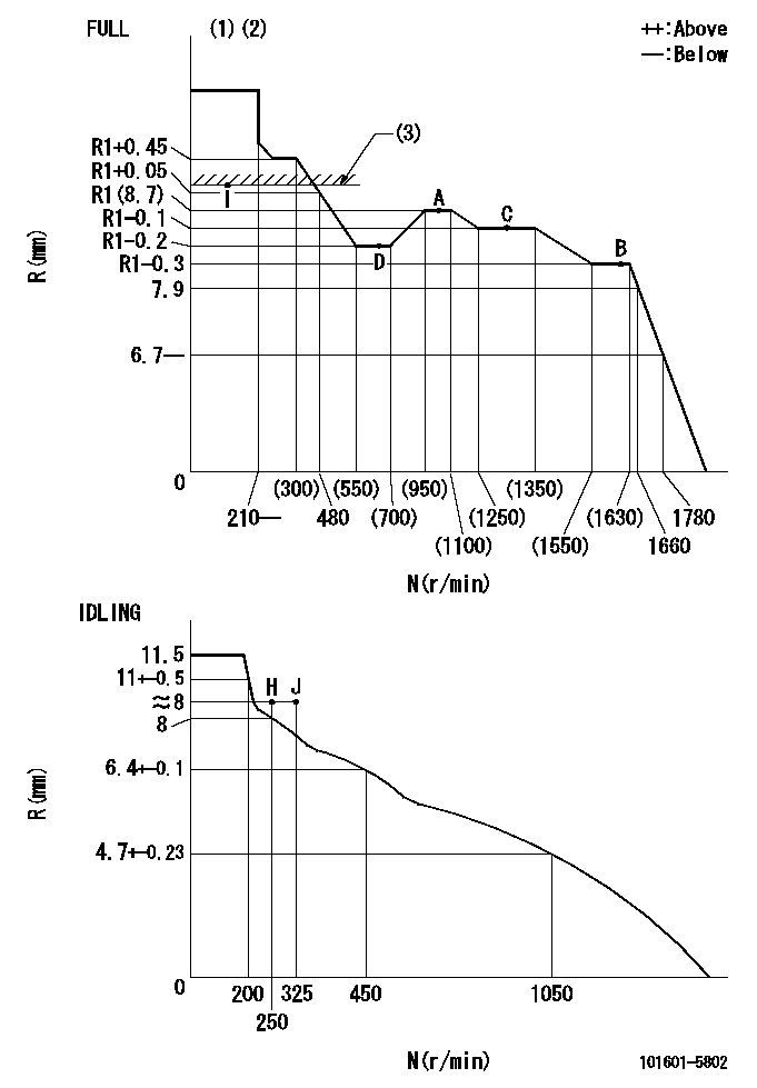
Governor adjustment

N:Pump speed
R:Rack position (mm)
(1)Torque cam stamping: T1
(2)Tolerance for racks not indicated: +-0.05mm.
(3)RACK LIMIT: RAL
----------
T1=93 RAL=[R1+0.2]+0.2mm
----------
----------
T1=93 RAL=[R1+0.2]+0.2mm
----------
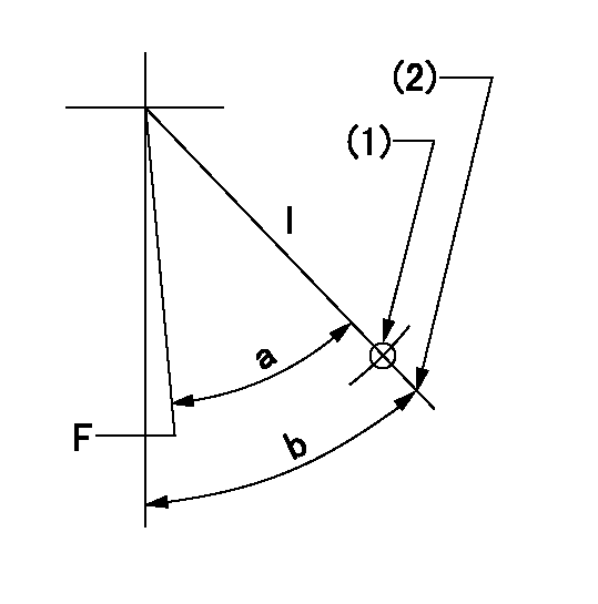
Speed control lever angle

F:Full speed
I:Idle
(1)Use the hole at R = aa
(2)Stopper bolt setting
----------
aa=55mm
----------
a=33deg+-3deg b=34deg+-5deg
----------
aa=55mm
----------
a=33deg+-3deg b=34deg+-5deg
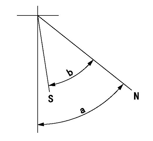
Stop lever angle

N:Pump normal
S:Stop the pump.
----------
----------
a=40deg+-5deg b=40deg+-5deg
----------
----------
a=40deg+-5deg b=40deg+-5deg
Timing setting

(1)Pump vertical direction
(2)Position of gear's standard threaded hole at No 1 cylinder's beginning of injection
(3)-
(4)-
----------
----------
a=(70deg)
----------
----------
a=(70deg)
Information:
Engine Model View
3408 Engine Shown
Turbochargers (1), Exhaust Outlet (2), Crankcase Breather (3), Lifting Eye (4), Flywheel (5), Magnetic Pickup (6), Electronic Control Module (ECM) (7), Oil Fill Tube (8), Thermostat (9), Primary Fuel Filter (10), Water Pump (11), Crankshaft Vibration Damper (12), Alternator (13), Oil Filters (14), Crankcase Drain Plug (15), Fuel Filters and Priming Pump (16).3408 Engine Description
Caterpillar 3408 electronically controlled Industrial Engines are 18 liter (1099 cu in), 137 mm (5.4 in) bore and 152.4 mm (6.0 in) stroke, four cycle, 8 cylinder, 65 degree vee diesel design. The engine is twin turbocharged with jacket water aftercooling and direct fuel injection. It is designed for petroleum and auxiliary industrial applications.The engine and components are designed for high power output. The reduced size and weight plus increased fuel economy provide maximum performance. Contact your Caterpillar dealer for information on power ratings.Larger diameter plungers and a higher injection rate camshaft are incorporated in the valve train/fuel system. The fuel lines are made of high strength steel and the ends of the lines have collared washers to increase reliability.The cooling system has a gear driven centrifugal water pump, two thermostats (one for each bank) which regulate engine coolant temperature, and an oil cooler. A customer supplied fan drive and cooling system (radiator) may be required for the industrial
Have questions with 101601-5802?
Group cross 101601-5802 ZEXEL
Hino
Hino
101601-5802
9 400 614 629
220007421A
INJECTION-PUMP ASSEMBLY
W06D
W06D