Information injection-pump assembly
BOSCH
9 400 614 628
9400614628
ZEXEL
101601-5783
1016015783
HINO
220007291B
220007291b
Rating:
Service parts 101601-5783 INJECTION-PUMP ASSEMBLY:
1.
_
6.
COUPLING PLATE
7.
COUPLING PLATE
8.
_
9.
_
11.
Nozzle and Holder
12.
Open Pre:MPa(Kqf/cm2)
19.6{200}
15.
NOZZLE SET
Include in #1:
101601-5783
as INJECTION-PUMP ASSEMBLY
Include in #2:
104135-3032
as _
Cross reference number
BOSCH
9 400 614 628
9400614628
ZEXEL
101601-5783
1016015783
HINO
220007291B
220007291b
Zexel num
Bosch num
Firm num
Name
101601-5783
9 400 614 628
220007291B HINO
INJECTION-PUMP ASSEMBLY
W06E K 14BE INJECTION PUMP ASSY PE6A PE
W06E K 14BE INJECTION PUMP ASSY PE6A PE
Calibration Data:
Adjustment conditions
Test oil
1404 Test oil ISO4113 or {SAEJ967d}
1404 Test oil ISO4113 or {SAEJ967d}
Test oil temperature
degC
40
40
45
Nozzle and nozzle holder
105780-8140
Bosch type code
EF8511/9A
Nozzle
105780-0000
Bosch type code
DN12SD12T
Nozzle holder
105780-2080
Bosch type code
EF8511/9
Opening pressure
MPa
17.2
Opening pressure
kgf/cm2
175
Injection pipe
Outer diameter - inner diameter - length (mm) mm 6-2-600
Outer diameter - inner diameter - length (mm) mm 6-2-600
Overflow valve
134424-0920
Overflow valve opening pressure
kPa
162
147
177
Overflow valve opening pressure
kgf/cm2
1.65
1.5
1.8
Tester oil delivery pressure
kPa
157
157
157
Tester oil delivery pressure
kgf/cm2
1.6
1.6
1.6
Direction of rotation (viewed from drive side)
Right R
Right R
Injection timing adjustment
Direction of rotation (viewed from drive side)
Right R
Right R
Injection order
1-4-2-6-
3-5
Pre-stroke
mm
3.45
3.42
3.48
Beginning of injection position
Drive side NO.1
Drive side NO.1
Difference between angles 1
Cal 1-4 deg. 60 59.75 60.25
Cal 1-4 deg. 60 59.75 60.25
Difference between angles 2
Cyl.1-2 deg. 120 119.75 120.25
Cyl.1-2 deg. 120 119.75 120.25
Difference between angles 3
Cal 1-6 deg. 180 179.75 180.25
Cal 1-6 deg. 180 179.75 180.25
Difference between angles 4
Cal 1-3 deg. 240 239.75 240.25
Cal 1-3 deg. 240 239.75 240.25
Difference between angles 5
Cal 1-5 deg. 300 299.75 300.25
Cal 1-5 deg. 300 299.75 300.25
Injection quantity adjustment
Adjusting point
-
Rack position
11.3
Pump speed
r/min
900
900
900
Average injection quantity
mm3/st.
63.5
61.5
65.5
Max. variation between cylinders
%
0
-3.5
3.5
Basic
*
Fixing the rack
*
Standard for adjustment of the maximum variation between cylinders
*
Injection quantity adjustment_02
Adjusting point
H
Rack position
9.3+-0.5
Pump speed
r/min
250
250
250
Each cylinder's injection qty
mm3/st.
17.1
16.1
18.1
Fixing the rack
*
Standard for adjustment of the maximum variation between cylinders
*
Injection quantity adjustment_03
Adjusting point
A
Rack position
R1(11.3)
Pump speed
r/min
900
900
900
Average injection quantity
mm3/st.
63.5
62.5
64.5
Basic
*
Fixing the lever
*
Injection quantity adjustment_04
Adjusting point
B
Rack position
R1(11.3)
Pump speed
r/min
1500
1500
1500
Average injection quantity
mm3/st.
67.4
63.4
71.4
Fixing the lever
*
Injection quantity adjustment_05
Adjusting point
C
Rack position
R1-0.35
Pump speed
r/min
600
600
600
Average injection quantity
mm3/st.
49.6
45.6
53.6
Fixing the lever
*
Injection quantity adjustment_06
Adjusting point
I
Rack position
-
Pump speed
r/min
100
100
100
Average injection quantity
mm3/st.
123
123
133
Fixing the lever
*
Rack limit
*
Timer adjustment
Pump speed
r/min
960--
Advance angle
deg.
0
0
0
Load
1/4
Remarks
Start
Start
Timer adjustment_02
Pump speed
r/min
910
Advance angle
deg.
0.3
Load
1/4
Timer adjustment_03
Pump speed
r/min
1010
Advance angle
deg.
1
0.7
1.3
Load
4/4
Timer adjustment_04
Pump speed
r/min
1210
Advance angle
deg.
1
0.7
1.3
Load
3/4
Timer adjustment_05
Pump speed
r/min
1510
Advance angle
deg.
6
5.7
6.3
Load
4/4
Remarks
Finish
Finish
Test data Ex:
Governor adjustment
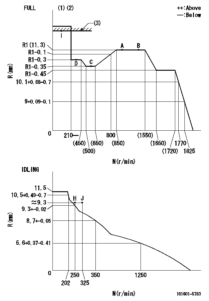
N:Pump speed
R:Rack position (mm)
(1)Torque cam stamping: T1
(2)Tolerance for racks not indicated: +-0.05mm.
(3)RACK LIMIT
----------
T1=J57
----------
----------
T1=J57
----------
Speed control lever angle
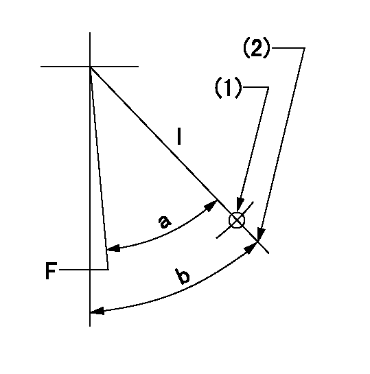
F:Full speed
I:Idle
(1)Use the hole at R = aa
(2)Stopper bolt set position 'H'
----------
aa=55mm
----------
a=(31deg) b=34deg+-5deg
----------
aa=55mm
----------
a=(31deg) b=34deg+-5deg
Stop lever angle
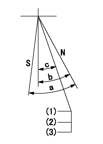
N:Pump normal
S:Stop the pump.
(1)Rack position = aa
(2)Stopper bolt setting
(3)(Apply red paint after setting.)
----------
aa=17+-0.1mm
----------
a=40deg+-5deg b=40deg+-5deg c=(35deg)
----------
aa=17+-0.1mm
----------
a=40deg+-5deg b=40deg+-5deg c=(35deg)
Timing setting

(1)Pump vertical direction
(2)Position of gear's standard threaded hole at No 1 cylinder's beginning of injection
(3)-
(4)-
----------
----------
a=(70deg)
----------
----------
a=(70deg)
Information:
Owner Warranty Rights and Obligations
The California Air Resources Board (CARB) and Caterpillar Inc. are pleased to explain the emission control system warranty on your 1991 truck engine.In California, new motor vehicle engines must be designed, built and equipped to meet the state's stringent anti-smog standards. Caterpillar Inc. must warrant the emission control system on your truck engine for the duration of time listed below provided there has not been any abuse, neglect or improper maintenance of your truck engine.Your emission control system may include parts such as the fuel injection system and engine computer, if equipped. Also included may be hoses, connectors, clamps and other emission-related components.Where a warrantable condition exists, Caterpillar Inc. will repair the truck engine at no cost to the owner including diagnosis, parts and labor.Manufacturer's Warranty Coverage
* The emissions warranty period for new truck engines is a duration of 60 months, 100,000 miles (161 000 km), or 3,000 hours of operation, whichever occurs first.* If an emission related part or component on your truck engine is defective, the part or component will be repaired or replaced by Caterpillar Inc. This is your emission control system WARRANTY.Owner's Warranty Responsibilities
* As the truck engine owner, you are responsible for the performance of the required maintenance listed in the truck engine owner's manual (Operation and Maintenance Manual). Caterpillar Inc. recommends that you retain all receipts and records covering the maintenance on your truck engine, but cannot deny warranty solely for the lack of receipts and records or for your failure to ensure the performance of all scheduled maintenance.* You are responsible for presenting your truck engine to a Caterpillar Inc. dealer as soon as a truck engine problem exists. The warranty repairs should be completed in a reasonable amount of time, not to exceed 30 days.* As the truck engine owner, you should also be aware that Caterpillar Inc. may deny you warranty coverage if your truck engine or an emission component or part has failed due to abuse, neglect, improper maintenance or unapproved modifications.If you have questions regarding your warranty rights and responsibilities, contact:Caterpillar Inc.
Manager, Truck Engine Business
Peoria, IL 61629
Phone (309) 578-6288
OR
California Air Resources Board (CARB)
9528 Telstar Ave.
El Monte, CA 91731
Emissions Warranty
Caterpillar Inc. warrants to the initial owner and subsequent owner of a diesel truck engine (powering an on-highway truck), that such engine is ...1. Designed, built and equipped so as to conform, at the time of sale, with all applicable regulations adopted by the California Air Resources Board (CARB).2. Free from defects in materials and workmanship in specific emission related parts for a period of 60 months, 100,000 miles (161 000 km) or 3,000 hours of operation, whichever occurs first, after date of delivery to the initial owner.If an emission related part fails during the warranty period, it will be repaired or replaced. Any such part repaired or replaced under warranty is warranted for the remainder of the warranty period.During the term of this warranty, Caterpillar Inc. will provide through a Caterpillar dealer or other
Have questions with 101601-5783?
Group cross 101601-5783 ZEXEL
Hino
Hino
101601-5783
9 400 614 628
220007291B
INJECTION-PUMP ASSEMBLY
W06E
W06E