Information injection-pump assembly
BOSCH
F 01G 09U 02Z
f01g09u02z
ZEXEL
101601-5781
1016015781
HINO
220007291A
220007291a
Rating:
Service parts 101601-5781 INJECTION-PUMP ASSEMBLY:
1.
_
6.
COUPLING PLATE
7.
COUPLING PLATE
8.
_
9.
_
11.
Nozzle and Holder
23600-2142A
12.
Open Pre:MPa(Kqf/cm2)
19.6{200}
15.
NOZZLE SET
Cross reference number
BOSCH
F 01G 09U 02Z
f01g09u02z
ZEXEL
101601-5781
1016015781
HINO
220007291A
220007291a
Zexel num
Bosch num
Firm num
Name
F 01G 09U 02Z
220007291A HINO
INJECTION-PUMP ASSEMBLY
W06E A * K 14BE PE6A PE
W06E A * K 14BE PE6A PE
Calibration Data:
Adjustment conditions
Test oil
1404 Test oil ISO4113 or {SAEJ967d}
1404 Test oil ISO4113 or {SAEJ967d}
Test oil temperature
degC
40
40
45
Nozzle and nozzle holder
105780-8140
Bosch type code
EF8511/9A
Nozzle
105780-0000
Bosch type code
DN12SD12T
Nozzle holder
105780-2080
Bosch type code
EF8511/9
Opening pressure
MPa
17.2
Opening pressure
kgf/cm2
175
Injection pipe
Outer diameter - inner diameter - length (mm) mm 6-2-600
Outer diameter - inner diameter - length (mm) mm 6-2-600
Overflow valve
134424-0920
Overflow valve opening pressure
kPa
162
147
177
Overflow valve opening pressure
kgf/cm2
1.65
1.5
1.8
Tester oil delivery pressure
kPa
157
157
157
Tester oil delivery pressure
kgf/cm2
1.6
1.6
1.6
Direction of rotation (viewed from drive side)
Right R
Right R
Injection timing adjustment
Direction of rotation (viewed from drive side)
Right R
Right R
Injection order
1-4-2-6-
3-5
Pre-stroke
mm
3.45
3.42
3.48
Beginning of injection position
Drive side NO.1
Drive side NO.1
Difference between angles 1
Cal 1-4 deg. 60 59.75 60.25
Cal 1-4 deg. 60 59.75 60.25
Difference between angles 2
Cyl.1-2 deg. 120 119.75 120.25
Cyl.1-2 deg. 120 119.75 120.25
Difference between angles 3
Cal 1-6 deg. 180 179.75 180.25
Cal 1-6 deg. 180 179.75 180.25
Difference between angles 4
Cal 1-3 deg. 240 239.75 240.25
Cal 1-3 deg. 240 239.75 240.25
Difference between angles 5
Cal 1-5 deg. 300 299.75 300.25
Cal 1-5 deg. 300 299.75 300.25
Injection quantity adjustment
Adjusting point
-
Rack position
11.3
Pump speed
r/min
900
900
900
Average injection quantity
mm3/st.
63.5
61.5
65.5
Max. variation between cylinders
%
0
-3.5
3.5
Basic
*
Fixing the rack
*
Standard for adjustment of the maximum variation between cylinders
*
Injection quantity adjustment_02
Adjusting point
H
Rack position
9.3+-0.5
Pump speed
r/min
250
250
250
Each cylinder's injection qty
mm3/st.
17.1
16.1
18.1
Fixing the rack
*
Standard for adjustment of the maximum variation between cylinders
*
Injection quantity adjustment_03
Adjusting point
A
Rack position
R1(11.3)
Pump speed
r/min
900
900
900
Average injection quantity
mm3/st.
63.5
62.5
64.5
Basic
*
Fixing the lever
*
Injection quantity adjustment_04
Adjusting point
B
Rack position
R1(11.3)
Pump speed
r/min
1500
1500
1500
Average injection quantity
mm3/st.
67.4
63.4
71.4
Fixing the lever
*
Injection quantity adjustment_05
Adjusting point
C
Rack position
R1-0.35
Pump speed
r/min
600
600
600
Average injection quantity
mm3/st.
49.6
45.6
53.6
Fixing the lever
*
Injection quantity adjustment_06
Adjusting point
I
Rack position
-
Pump speed
r/min
100
100
100
Average injection quantity
mm3/st.
123
123
133
Fixing the lever
*
Rack limit
*
Timer adjustment
Pump speed
r/min
960--
Advance angle
deg.
0
0
0
Load
1/4
Remarks
Start
Start
Timer adjustment_02
Pump speed
r/min
910
Advance angle
deg.
0.3
Load
1/4
Timer adjustment_03
Pump speed
r/min
1010
Advance angle
deg.
1
0.7
1.3
Load
4/4
Timer adjustment_04
Pump speed
r/min
1210
Advance angle
deg.
1
0.7
1.3
Load
3/4
Timer adjustment_05
Pump speed
r/min
1510
Advance angle
deg.
6
5.7
6.3
Load
4/4
Remarks
Finish
Finish
Test data Ex:
Governor adjustment
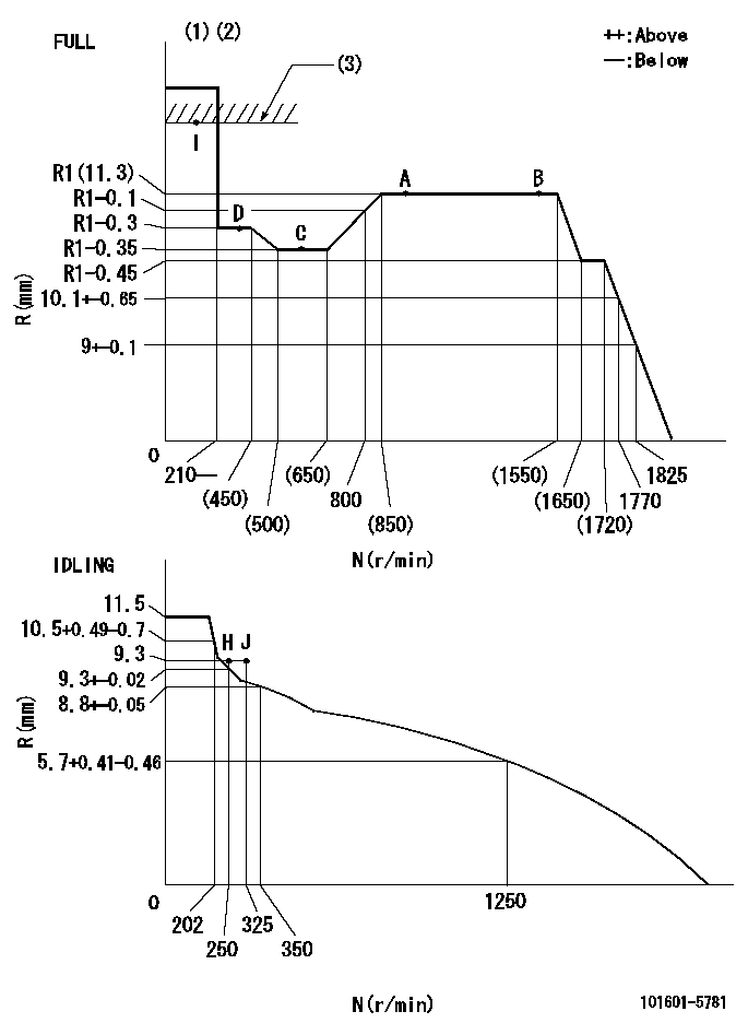
N:Pump speed
R:Rack position (mm)
(1)Torque cam stamping: T1
(2)Tolerance for racks not indicated: +-0.05mm.
(3)RACK LIMIT
----------
T1=F50
----------
----------
T1=F50
----------
Speed control lever angle
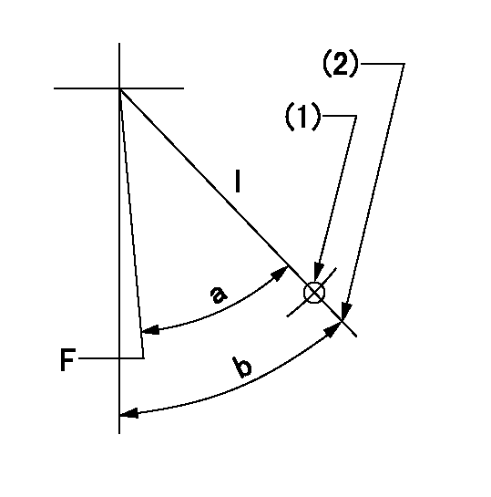
F:Full speed
I:Idle
(1)Use the hole at R = aa
(2)Stopper bolt set position 'H'
----------
aa=55mm
----------
a=32.5deg+-3deg b=34deg+-5deg
----------
aa=55mm
----------
a=32.5deg+-3deg b=34deg+-5deg
Stop lever angle
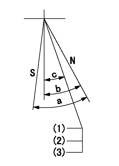
N:Pump normal
S:Stop the pump.
(1)Rack position = aa
(2)Set the stopper bolt. (After setting, apply red paint.)
(3)Engine normal
----------
aa=17+-0.1mm
----------
a=40deg+-5deg b=40deg+-5deg c=(35deg)
----------
aa=17+-0.1mm
----------
a=40deg+-5deg b=40deg+-5deg c=(35deg)
Timing setting

(1)Pump vertical direction
(2)Position of gear's standard threaded hole at No 1 cylinder's beginning of injection
(3)-
(4)-
----------
----------
a=(70deg)
----------
----------
a=(70deg)
Information:
Replace:
Thrust, Main and Rod Bearings, Valve Rotators, Thermostat and Throttle Position SensorIn most probability, these components will not last until the second overhaul. Therefore, Caterpillar recommends the installation of these components new at each overhaul period.Inspect:
Crankshaft, Camshaft, Camshaft Followers, Vibration Damper, Spacer Block, Oil Pump and Fuel Transfer PumpThe ideal time for inspecting your crankshaft, camshaft and vibration damper is while the engine is disassembled for overhaul. Inspect each component for potential damage as follows:Crankshaft - Inspect for bend, journal damage and bearing material seized to the journal. At the same time, check the taper and profile of the crankshaft journals by interpreting your main and rod bearing wear patterns. In case of an out-of-frame overhaul, use the magnetic particle inspection process to check the crankshaft for cracks.* Camshaft - Inspect the camshaft for journal damage. In case of an out-of-frame overhaul, use the magnetic particle inspection process to check the camshaft for cracks.* Camshaft Followers - For out-of-frame overhaul, inspect the cam bearing for fatigue and wear.* Vibration Damper - Inspect the damper for rubber deterioration and movement of the outer ring relative to the inner hub.* Spacer Block - Inspect the spacer block for excessive wear or warping. For additional information regarding these components, contact your local Caterpillar dealer for assistance.Test:
Electronic Unit Injectors For additional information regarding this component, contact your local Caterpillar dealer for assistance.Clean/Test:
Oil Cooler Core and Aftercooler CoreCaterpillar recommends that the oil cooler core and the air-to-air aftercooler core be cleaned and pressure tested at each overhaul. For additional specifications and/or pressure test information, contact your local Caterpillar dealer.Cleaning Procedure for Air-to-Air Aftercooler
Caterpillar recommends that the air-to-air aftercooler core be removed, cleaned, and tested at overhaul time, if a turbocharger failure has occurred, or if at any time the turbocharger develops an oil leak.To clean the air-to-air aftercooler system:1. Remove the air-to-air aftercooler core. Turn the core upside down to remove debris from the inlet tank.
Do not use caustic cleaners to clean the air-to-air aftercooler core. Caustic cleaners will attack the internal metals of the core and cause leakage.
2. Back flush internally with a solvent to loosen foreign substances and to remove oil.Caterpillar recommends the use of Caterpillar Hydrosolv 4165 or Hydrosolv 100 Liquid Cleaners. For more information see "General Instructions and Application Guide" Form LEHQ6101 or contact your Caterpillar dealer.3. Shake the core vigorously to eliminate any trapped debris.4. Wash the core with hot, soapy water. Rinse thoroughly with clean water.
The maximum air pressure must not be above 30 psi (205 kPa) for cleaning purposes.
5. Dry the core with compressed air. Blow air in reverse direction of normal flow. Use all necessary safety equipment while using compressed air.6. Inspect the system to ensure cleanliness and install the air-to-air aftercooler core.Caterpillar Recommendation
The "repair before failure" concept makes sense. It saves money, lowers operating costs and minimizes downtime.As previously illustrated, it is not cheaper to operate the truck until an engine component fails, since failing components may increase fuel costs and upon failure, could