Information injection-pump assembly
BOSCH
F 019 Z10 819
f019z10819
ZEXEL
101601-5780
1016015780
HINO
220007290A
220007290a
Rating:
Service parts 101601-5780 INJECTION-PUMP ASSEMBLY:
1.
_
6.
COUPLING PLATE
7.
COUPLING PLATE
8.
_
9.
_
11.
Nozzle and Holder
12.
Open Pre:MPa(Kqf/cm2)
19.6(200)
15.
NOZZLE SET
Cross reference number
BOSCH
F 019 Z10 819
f019z10819
ZEXEL
101601-5780
1016015780
HINO
220007290A
220007290a
Zexel num
Bosch num
Firm num
Name
Calibration Data:
Adjustment conditions
Test oil
1404 Test oil ISO4113 or {SAEJ967d}
1404 Test oil ISO4113 or {SAEJ967d}
Test oil temperature
degC
40
40
45
Nozzle and nozzle holder
105780-8140
Bosch type code
EF8511/9A
Nozzle
105780-0000
Bosch type code
DN12SD12T
Nozzle holder
105780-2080
Bosch type code
EF8511/9
Opening pressure
MPa
17.2
Opening pressure
kgf/cm2
175
Injection pipe
Outer diameter - inner diameter - length (mm) mm 6-2-600
Outer diameter - inner diameter - length (mm) mm 6-2-600
Overflow valve
134424-0920
Overflow valve opening pressure
kPa
162
147
177
Overflow valve opening pressure
kgf/cm2
1.65
1.5
1.8
Tester oil delivery pressure
kPa
157
157
157
Tester oil delivery pressure
kgf/cm2
1.6
1.6
1.6
Direction of rotation (viewed from drive side)
Right R
Right R
Injection timing adjustment
Direction of rotation (viewed from drive side)
Right R
Right R
Injection order
1-4-2-6-
3-5
Pre-stroke
mm
3.45
3.42
3.48
Beginning of injection position
Drive side NO.1
Drive side NO.1
Difference between angles 1
Cal 1-4 deg. 60 59.75 60.25
Cal 1-4 deg. 60 59.75 60.25
Difference between angles 2
Cyl.1-2 deg. 120 119.75 120.25
Cyl.1-2 deg. 120 119.75 120.25
Difference between angles 3
Cal 1-6 deg. 180 179.75 180.25
Cal 1-6 deg. 180 179.75 180.25
Difference between angles 4
Cal 1-3 deg. 240 239.75 240.25
Cal 1-3 deg. 240 239.75 240.25
Difference between angles 5
Cal 1-5 deg. 300 299.75 300.25
Cal 1-5 deg. 300 299.75 300.25
Injection quantity adjustment
Adjusting point
-
Rack position
11.3
Pump speed
r/min
900
900
900
Average injection quantity
mm3/st.
63.5
61.5
65.5
Max. variation between cylinders
%
0
-3.5
3.5
Basic
*
Fixing the rack
*
Standard for adjustment of the maximum variation between cylinders
*
Injection quantity adjustment_02
Adjusting point
H
Rack position
9.3+-0.5
Pump speed
r/min
250
250
250
Each cylinder's injection qty
mm3/st.
17.1
16.1
18.1
Fixing the rack
*
Standard for adjustment of the maximum variation between cylinders
*
Injection quantity adjustment_03
Adjusting point
A
Rack position
R1(11.3)
Pump speed
r/min
900
900
900
Average injection quantity
mm3/st.
63.5
62.5
64.5
Basic
*
Fixing the lever
*
Injection quantity adjustment_04
Adjusting point
B
Rack position
R1(11.3)
Pump speed
r/min
1500
1500
1500
Average injection quantity
mm3/st.
67.4
63.4
71.4
Fixing the lever
*
Injection quantity adjustment_05
Adjusting point
C
Rack position
R1-0.35
Pump speed
r/min
600
600
600
Average injection quantity
mm3/st.
49.6
45.6
53.6
Fixing the lever
*
Injection quantity adjustment_06
Adjusting point
I
Rack position
-
Pump speed
r/min
100
100
100
Average injection quantity
mm3/st.
123
123
133
Fixing the lever
*
Rack limit
*
Timer adjustment
Pump speed
r/min
950--
Advance angle
deg.
0
0
0
Load
1/4
Remarks
Start
Start
Timer adjustment_02
Pump speed
r/min
900
Advance angle
deg.
0.3
Load
1/4
Timer adjustment_03
Pump speed
r/min
1000
Advance angle
deg.
1
0.7
1.3
Load
4/4
Timer adjustment_04
Pump speed
r/min
1200
Advance angle
deg.
1
0.7
1.3
Load
3/4
Timer adjustment_05
Pump speed
r/min
1500
Advance angle
deg.
6
5.7
6.3
Load
4/4
Remarks
Finish
Finish
Test data Ex:
Governor adjustment
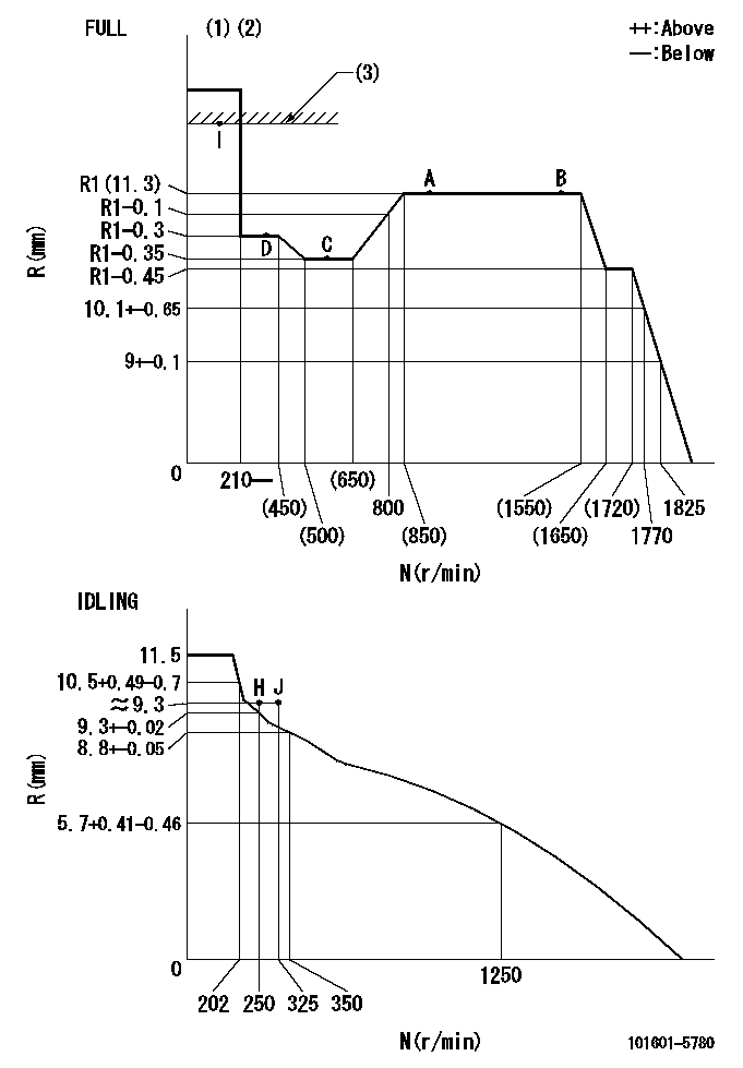
N:Pump speed
R:Rack position (mm)
(1)Torque cam stamping: T1
(2)Tolerance for racks not indicated: +-0.05mm.
(3)RACK LIMIT
----------
T1=F50
----------
----------
T1=F50
----------
Speed control lever angle
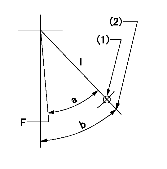
F:Full speed
I:Idle
(1)Use the hole at R = aa
(2)Stopper bolt set position 'H'
----------
aa=55mm
----------
a=32.5deg+-3deg b=34deg+-5deg
----------
aa=55mm
----------
a=32.5deg+-3deg b=34deg+-5deg
Stop lever angle
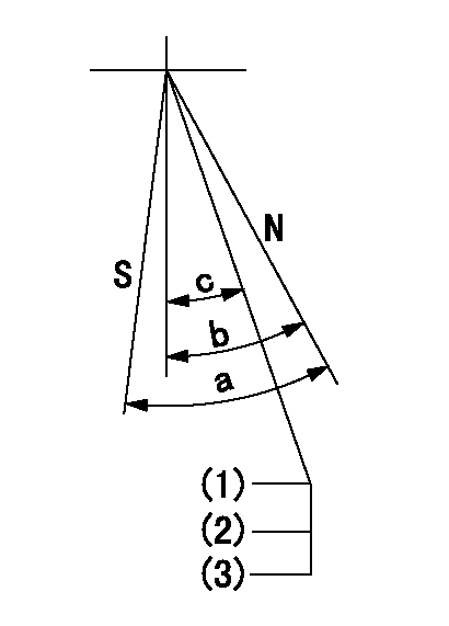
N:Pump normal
S:Stop the pump.
(1)Rack position = aa
(2)Set the stopper bolt. (After setting, apply red paint.)
(3)Engine normal
----------
aa=17+-0.1mm
----------
a=40deg+-5deg b=40deg+-5deg c=(35deg)
----------
aa=17+-0.1mm
----------
a=40deg+-5deg b=40deg+-5deg c=(35deg)
Timing setting

(1)Pump vertical direction
(2)Position of gear's standard threaded hole at No 1 cylinder's beginning of injection
(3)-
(4)-
----------
----------
a=(70deg)
----------
----------
a=(70deg)
Information:
All PM Level 3 maintenance is to be performed at the intervals specified in the Maintenance Management Schedule.Before proceeding with PM Level 3 maintenance, perform all PM Level 2, PM Level 1 and Daily maintenance requirements. You must read and understand the warnings and instructions contained in the Safety section of this manual before performing any operation or maintenance procedures.Air Compressor
Rebuild or Exchange
Visually check for fluid leaks.Our recommendation to maintain your air compressor before it fails will be less costly than repairing the air compressor after failure.If the engine is operated until the air compressor fails, additional damage to the engine could result. For example: A failed air compressor could contaminate the engine oil with particles of materials since engine oil also lubricates the air compressor. The circulation of these engine oil with particles of materials since engine oil also lubricates the air compressor. The circulation of these contaminates through the engine lubricating system could damage the engine's main and connecting rod bearings.Maintenance Options
Repair Kits - These useful kits can be obtained from your Caterpillar dealer. These kits include all the necessary parts, special tools and instructions to repair your air compressor in either your own maintenance shop or at your servicing dealer's facility. Repair kits simplify parts ordering, help speed repairs and reduce parts cost. Exchange - This is a cost cutting service that permits exchanging a worn air compressor for a dealer or OEM factory rebuilt air compressor on an over-the-counter basis. They are available when needed at a substantial savings in both time and money. New - Replace with a new air compressor.Caterpillar Recommendation
The most cost effective repair option is to rebuild the air compressor with a repair kit that can be obtained from your Caterpillar dealer.Refer to the Service Manual for your engine to remove and install the air compressor.Turbocharger
Rebuild or Exchange
The cost incurred to maintain your turbocharger before failure as recommended could be significantly less than if you wait until your turbocharger fails.By maintaining your turbocharger before failure, you will minimize unscheduled downtime and reduce the chances for potential damage to other engine parts. When you reduce the risk of unscheduled downtime and costly repairs, you conserve cash that can be budgeted for use more profitably elsewhere.If you choose to operate your engine until the turbocharger fails, your repair costs could be as much as twenty-five times or more compared to the repair before failure cost. This excessive cost is due to additional engine damage that could have been prevented.If the engine is operated until the turbocharger fails, severe damage to the turbocharger's compressor wheel and/or engine could result.For example: severe damage to the turbocharger compressor wheel could cause parts from the compressor wheel to enter the engine cylinder that could result in cracks in the cylinder head and cause additional damage to the piston, a piston seizure orother potential damage to valves and cylinder head.Our recommended maintenance intervals for performing preventive maintenance on your turbocharger are based on experience and gathered
Rebuild or Exchange
Visually check for fluid leaks.Our recommendation to maintain your air compressor before it fails will be less costly than repairing the air compressor after failure.If the engine is operated until the air compressor fails, additional damage to the engine could result. For example: A failed air compressor could contaminate the engine oil with particles of materials since engine oil also lubricates the air compressor. The circulation of these engine oil with particles of materials since engine oil also lubricates the air compressor. The circulation of these contaminates through the engine lubricating system could damage the engine's main and connecting rod bearings.Maintenance Options
Repair Kits - These useful kits can be obtained from your Caterpillar dealer. These kits include all the necessary parts, special tools and instructions to repair your air compressor in either your own maintenance shop or at your servicing dealer's facility. Repair kits simplify parts ordering, help speed repairs and reduce parts cost. Exchange - This is a cost cutting service that permits exchanging a worn air compressor for a dealer or OEM factory rebuilt air compressor on an over-the-counter basis. They are available when needed at a substantial savings in both time and money. New - Replace with a new air compressor.Caterpillar Recommendation
The most cost effective repair option is to rebuild the air compressor with a repair kit that can be obtained from your Caterpillar dealer.Refer to the Service Manual for your engine to remove and install the air compressor.Turbocharger
Rebuild or Exchange
The cost incurred to maintain your turbocharger before failure as recommended could be significantly less than if you wait until your turbocharger fails.By maintaining your turbocharger before failure, you will minimize unscheduled downtime and reduce the chances for potential damage to other engine parts. When you reduce the risk of unscheduled downtime and costly repairs, you conserve cash that can be budgeted for use more profitably elsewhere.If you choose to operate your engine until the turbocharger fails, your repair costs could be as much as twenty-five times or more compared to the repair before failure cost. This excessive cost is due to additional engine damage that could have been prevented.If the engine is operated until the turbocharger fails, severe damage to the turbocharger's compressor wheel and/or engine could result.For example: severe damage to the turbocharger compressor wheel could cause parts from the compressor wheel to enter the engine cylinder that could result in cracks in the cylinder head and cause additional damage to the piston, a piston seizure orother potential damage to valves and cylinder head.Our recommended maintenance intervals for performing preventive maintenance on your turbocharger are based on experience and gathered