Information injection-pump assembly
BOSCH
9 400 614 626
9400614626
ZEXEL
101601-5762
1016015762
HINO
220007151A
220007151a
Rating:
Service parts 101601-5762 INJECTION-PUMP ASSEMBLY:
1.
_
6.
COUPLING PLATE
7.
COUPLING PLATE
8.
_
9.
_
11.
Nozzle and Holder
12.
Open Pre:MPa(Kqf/cm2)
21.6(220)
15.
NOZZLE SET
Cross reference number
BOSCH
9 400 614 626
9400614626
ZEXEL
101601-5762
1016015762
HINO
220007151A
220007151a
Zexel num
Bosch num
Firm num
Name
101601-5762
9 400 614 626
220007151A HINO
INJECTION-PUMP ASSEMBLY
W06E K
W06E K
Calibration Data:
Adjustment conditions
Test oil
1404 Test oil ISO4113 or {SAEJ967d}
1404 Test oil ISO4113 or {SAEJ967d}
Test oil temperature
degC
40
40
45
Nozzle and nozzle holder
105780-8140
Bosch type code
EF8511/9A
Nozzle
105780-0000
Bosch type code
DN12SD12T
Nozzle holder
105780-2080
Bosch type code
EF8511/9
Opening pressure
MPa
17.2
Opening pressure
kgf/cm2
175
Injection pipe
Outer diameter - inner diameter - length (mm) mm 6-2-600
Outer diameter - inner diameter - length (mm) mm 6-2-600
Overflow valve
131424-5720
Overflow valve opening pressure
kPa
255
221
289
Overflow valve opening pressure
kgf/cm2
2.6
2.25
2.95
Tester oil delivery pressure
kPa
157
157
157
Tester oil delivery pressure
kgf/cm2
1.6
1.6
1.6
Direction of rotation (viewed from drive side)
Right R
Right R
Injection timing adjustment
Direction of rotation (viewed from drive side)
Right R
Right R
Injection order
1-4-2-6-
3-5
Pre-stroke
mm
3.1
3.07
3.13
Beginning of injection position
Drive side NO.1
Drive side NO.1
Difference between angles 1
Cal 1-4 deg. 60 59.75 60.25
Cal 1-4 deg. 60 59.75 60.25
Difference between angles 2
Cyl.1-2 deg. 120 119.75 120.25
Cyl.1-2 deg. 120 119.75 120.25
Difference between angles 3
Cal 1-6 deg. 180 179.75 180.25
Cal 1-6 deg. 180 179.75 180.25
Difference between angles 4
Cal 1-3 deg. 240 239.75 240.25
Cal 1-3 deg. 240 239.75 240.25
Difference between angles 5
Cal 1-5 deg. 300 299.75 300.25
Cal 1-5 deg. 300 299.75 300.25
Injection quantity adjustment
Adjusting point
-
Rack position
9.2
Pump speed
r/min
900
900
900
Average injection quantity
mm3/st.
52.4
50.4
54.4
Max. variation between cylinders
%
0
-3.5
3.5
Basic
*
Fixing the rack
*
Standard for adjustment of the maximum variation between cylinders
*
Injection quantity adjustment_02
Adjusting point
H
Rack position
8+-0.5
Pump speed
r/min
250
250
250
Average injection quantity
mm3/st.
6.8
5.3
8.3
Max. variation between cylinders
%
0
-10
10
Fixing the rack
*
Standard for adjustment of the maximum variation between cylinders
*
Injection quantity adjustment_03
Adjusting point
A
Rack position
R1(9.2)
Pump speed
r/min
900
900
900
Average injection quantity
mm3/st.
52.4
51.4
53.4
Basic
*
Fixing the lever
*
Injection quantity adjustment_04
Adjusting point
B
Rack position
R1-0.35
Pump speed
r/min
1500
1500
1500
Average injection quantity
mm3/st.
48.8
44.8
52.8
Fixing the lever
*
Injection quantity adjustment_05
Adjusting point
C
Rack position
R1-0.35
Pump speed
r/min
600
600
600
Average injection quantity
mm3/st.
36.5
32.5
40.5
Fixing the lever
*
Injection quantity adjustment_06
Adjusting point
D
Rack position
R1-0.1
Pump speed
r/min
1200
1200
1200
Average injection quantity
mm3/st.
53.1
49.1
57.1
Fixing the lever
*
Injection quantity adjustment_07
Adjusting point
E
Rack position
R1+0.2
Pump speed
r/min
400
400
400
Average injection quantity
mm3/st.
29.2
25.2
33.2
Fixing the lever
*
Injection quantity adjustment_08
Adjusting point
I
Rack position
-
Pump speed
r/min
100
100
100
Average injection quantity
mm3/st.
99
99
109
Fixing the lever
*
Rack limit
*
Timer adjustment
Pump speed
r/min
1050--
Advance angle
deg.
0
0
0
Remarks
Start
Start
Timer adjustment_02
Pump speed
r/min
1000
Advance angle
deg.
0.3
Timer adjustment_03
Pump speed
r/min
1500
Advance angle
deg.
4.5
4.2
4.8
Remarks
Finish
Finish
Test data Ex:
Governor adjustment
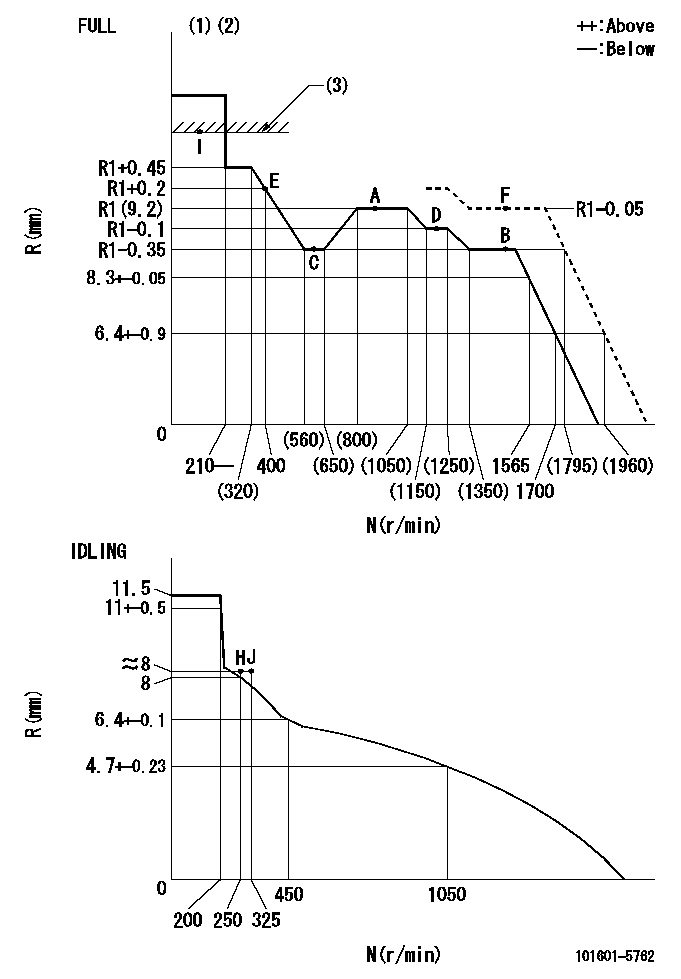
N:Pump speed
R:Rack position (mm)
(1)Torque cam stamping: T1
(2)Tolerance for racks not indicated: +-0.05mm.
(3)RACK LIMIT
----------
T1=C09
----------
----------
T1=C09
----------
Speed control lever angle

F:Full speed
I:Idle
(1)Stopper bolt set position 'H'
----------
----------
a=31deg+-3deg b=34deg+-5deg
----------
----------
a=31deg+-3deg b=34deg+-5deg
Stop lever angle
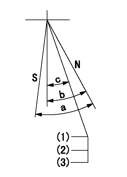
N:Pump normal
S:Stop the pump.
(1)Stopper bolt setting
(2)(Apply red paint after setting.)
(3)Engine normal
----------
----------
a=40deg+-5deg b=40deg+-5deg c=35deg+-2deg
----------
----------
a=40deg+-5deg b=40deg+-5deg c=35deg+-2deg
0000001501 TAMPER PROOF
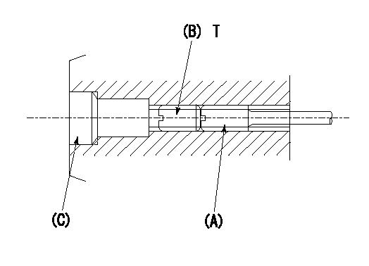
1. Method for setting tamperproof proofing
(1)Perform after governor adjustment (torque cam phase adjustment).
(2)Increase the full rack position to aa using the load lever.
(3)At N = N1, push in screw (A) until Ra.
(4)Temporarily caulk using the tip of a screwdriver
(5)Confirm that the rack at that time is Rb.
(6)Lock using setscrew (B). (Tightening torque = T)
(7)Pressfit (C) after applying adhesive.
(8)Readjust the full rack using the load lever.
----------
aa=(0.4)mm N1=1500r/min Ra=R1(9.2)-0.05mm Rb=R1(9.2)-0.05mm
----------
T=4.9~7N-m(0.5~0.7Kgf-m)
----------
aa=(0.4)mm N1=1500r/min Ra=R1(9.2)-0.05mm Rb=R1(9.2)-0.05mm
----------
T=4.9~7N-m(0.5~0.7Kgf-m)
Timing setting

(1)Pump vertical direction
(2)Position of gear's standard threaded hole at No 1 cylinder's beginning of injection
(3)-
(4)-
----------
----------
a=(70deg)
----------
----------
a=(70deg)
Information:
Adjust -to conform and correspond to specifications. Check -to observe for satisfactory conditions, accuracy, safety or performance. Exchange -to trade a worn or failing component for a remanufactured or rebuilt component. Inspect -to examine closely, in critical appraisal, while testing or evaluating components or systems. Lubricate -to apply a lubricant (oil, grease, etc.) as specified for reducing friction, heat and wear between solid surfaces. Protective Devices -indicators such as gauges, lights, emergency shutoffs, etc., that alert an operator that a potential problem may exist. Failure to respond to these indicators in a timely manner could result in engine failure. Rebuild -to repair a worn or failing component with new parts, components and/or remanufactured components. Replace -to install something new, remanufactured or rebuilt in place of an existing worn or failing component. Service Hours (Electrical) -records the time (clock hours) the engine is actually running but does not reflect variations in speed, load, etc.Interval Categories
Engine components can generally be grouped into speed sensitive and load sensitive categories. Therefore, the maintenance interval for each item listed in the Maintenance Management Schedule is primarily based on the item and its relationship to either engine speed or load. Speed sensitive items such as water pumps, air compressors, etc., are not primarily affected by the load on your engine during operation. The load on an engine will not significantly accelerate the repair or replacement cycle for speed sensitive items.Therefore, the maintenance intervals established for speed sensitive items are based on miles (kilometers) or service hours, whichever occurs first. Load sensitive items such as piston rings, cylinder liners, etc., are affected by the load on your engine during operation. Generally speaking, the lower the load, the longer the engine life and conversely, the higher the load, the shorter the engine life. A heavy load on an engine will accelerate the repair or replacement cycle for load sensitive items.Load sensitive items are normally internal engine components and the amount of fuel consumed is directly related to the load on your engine.Therefore, the maintenance interval for load sensitive items include fuel consumption, since the amount of fuel consumed is directly related to the load on your engine.Since the amount of fuel consumed is a better indicator of performing an overhaul than miles (kilometers) or service hours, Caterpillar recommends performing an overhaul on these items at the specified maintenance interval based on the quantity of fuel consumed.Interval to Overhaul
The specified overhaul interval for the 3176 Truck engine is "Every 80,000 Gallons (303 200 L) of Fuel or 500,000 Miles (805 000 km) or 10,000 Service Hours." The Maintenance Management Schedule follows. Ensure that the schedule is adhered to. PM Level means Preventive Maintenance Level.
Have questions with 101601-5762?
Group cross 101601-5762 ZEXEL
Hino
Hino
101601-5762
9 400 614 626
220007151A
INJECTION-PUMP ASSEMBLY
W06E
W06E