Information injection-pump assembly
BOSCH
F 019 Z10 818
f019z10818
ZEXEL
101601-5760
1016015760
HINO
220007150A
220007150a
Rating:
Service parts 101601-5760 INJECTION-PUMP ASSEMBLY:
1.
_
6.
COUPLING PLATE
7.
COUPLING PLATE
8.
_
9.
_
11.
Nozzle and Holder
12.
Open Pre:MPa(Kqf/cm2)
21.6(220)
15.
NOZZLE SET
Cross reference number
BOSCH
F 019 Z10 818
f019z10818
ZEXEL
101601-5760
1016015760
HINO
220007150A
220007150a
Zexel num
Bosch num
Firm num
Name
Calibration Data:
Adjustment conditions
Test oil
1404 Test oil ISO4113 or {SAEJ967d}
1404 Test oil ISO4113 or {SAEJ967d}
Test oil temperature
degC
40
40
45
Nozzle and nozzle holder
105780-8140
Bosch type code
EF8511/9A
Nozzle
105780-0000
Bosch type code
DN12SD12T
Nozzle holder
105780-2080
Bosch type code
EF8511/9
Opening pressure
MPa
17.2
Opening pressure
kgf/cm2
175
Injection pipe
Outer diameter - inner diameter - length (mm) mm 6-2-600
Outer diameter - inner diameter - length (mm) mm 6-2-600
Overflow valve
131424-5720
Overflow valve opening pressure
kPa
255
221
289
Overflow valve opening pressure
kgf/cm2
2.6
2.25
2.95
Tester oil delivery pressure
kPa
157
157
157
Tester oil delivery pressure
kgf/cm2
1.6
1.6
1.6
Direction of rotation (viewed from drive side)
Right R
Right R
Injection timing adjustment
Direction of rotation (viewed from drive side)
Right R
Right R
Injection order
1-4-2-6-
3-5
Pre-stroke
mm
3.1
3.07
3.13
Beginning of injection position
Drive side NO.1
Drive side NO.1
Difference between angles 1
Cal 1-4 deg. 60 59.75 60.25
Cal 1-4 deg. 60 59.75 60.25
Difference between angles 2
Cyl.1-2 deg. 120 119.75 120.25
Cyl.1-2 deg. 120 119.75 120.25
Difference between angles 3
Cal 1-6 deg. 180 179.75 180.25
Cal 1-6 deg. 180 179.75 180.25
Difference between angles 4
Cal 1-3 deg. 240 239.75 240.25
Cal 1-3 deg. 240 239.75 240.25
Difference between angles 5
Cal 1-5 deg. 300 299.75 300.25
Cal 1-5 deg. 300 299.75 300.25
Injection quantity adjustment
Adjusting point
-
Rack position
9.2
Pump speed
r/min
900
900
900
Average injection quantity
mm3/st.
52.4
50.4
54.4
Max. variation between cylinders
%
0
-3.5
3.5
Basic
*
Fixing the rack
*
Standard for adjustment of the maximum variation between cylinders
*
Injection quantity adjustment_02
Adjusting point
H
Rack position
8+-0.5
Pump speed
r/min
250
250
250
Average injection quantity
mm3/st.
6.8
5.3
8.3
Max. variation between cylinders
%
0
-10
10
Fixing the rack
*
Standard for adjustment of the maximum variation between cylinders
*
Injection quantity adjustment_03
Adjusting point
A
Rack position
R1(9.2)
Pump speed
r/min
900
900
900
Average injection quantity
mm3/st.
52.4
51.4
53.4
Basic
*
Fixing the lever
*
Injection quantity adjustment_04
Adjusting point
B
Rack position
R1-0.35
Pump speed
r/min
1500
1500
1500
Average injection quantity
mm3/st.
48.8
44.8
52.8
Fixing the lever
*
Injection quantity adjustment_05
Adjusting point
C
Rack position
R1-0.35
Pump speed
r/min
600
600
600
Average injection quantity
mm3/st.
36.5
32.5
40.5
Fixing the lever
*
Injection quantity adjustment_06
Adjusting point
D
Rack position
R1-0.1
Pump speed
r/min
1200
1200
1200
Average injection quantity
mm3/st.
53.1
49.1
57.1
Fixing the lever
*
Injection quantity adjustment_07
Adjusting point
E
Rack position
R1+0.2
Pump speed
r/min
400
400
400
Average injection quantity
mm3/st.
29.2
25.2
33.2
Fixing the lever
*
Injection quantity adjustment_08
Adjusting point
I
Rack position
-
Pump speed
r/min
100
100
100
Average injection quantity
mm3/st.
99
99
109
Fixing the lever
*
Rack limit
*
Timer adjustment
Pump speed
r/min
1000+50
Advance angle
deg.
0
0
0
Remarks
Start
Start
Timer adjustment_02
Pump speed
r/min
1500
Advance angle
deg.
3.5
3.2
3.8
Remarks
Finish
Finish
Test data Ex:
Governor adjustment
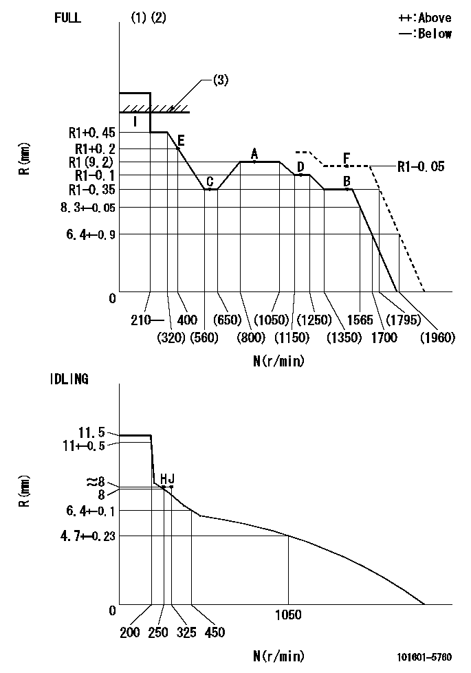
N:Pump speed
R:Rack position (mm)
(1)Torque cam stamping: T1
(2)Tolerance for racks not indicated: +-0.05mm.
(3)RACK LIMIT
----------
T1=C09
----------
----------
T1=C09
----------
Speed control lever angle

F:Full speed
I:Idle
(1)Stopper bolt set position 'H'
----------
----------
a=31deg+-3deg b=34deg+-5deg
----------
----------
a=31deg+-3deg b=34deg+-5deg
Stop lever angle
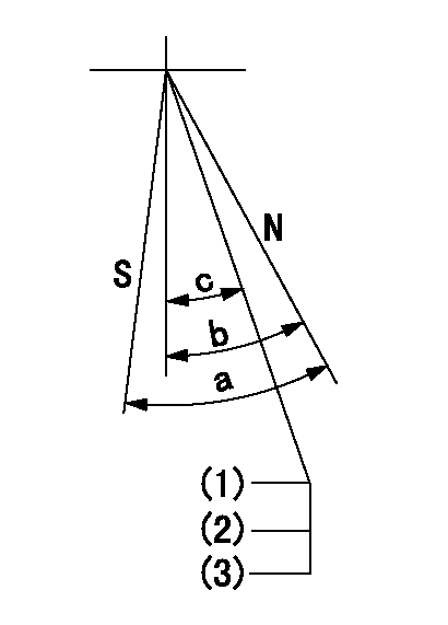
N:Pump normal
S:Stop the pump.
(1)Engine normal
(2)Stopper bolt setting
(3)(Apply red paint after setting.)
----------
----------
a=40deg+-5deg b=40deg+-5deg c=35deg+-2deg
----------
----------
a=40deg+-5deg b=40deg+-5deg c=35deg+-2deg
0000001501 TAMPER PROOF
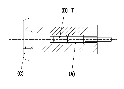
1. Method for setting tamperproof proofing
(1)After governor adjustment (torque cam phase adjustment), move the load lever to increase the full rack position to Ra.
(2)At pump speed N1, push in the screw (A) until the rack position is Rb.
(3)Temporarily caulk using the tip of a screwdriver
(4)Confirm that the rack at that time is at Rc.
(5)Lock using setscrew (B). (Tightening torque = T)
(6)Next, coat (C) with adhesive and then pressfit.
(7)Then, readjust the full rack position using the load lever.
----------
N1=1500r/min Ra=(0.4)mm Rb=R1(9.2)-0.05mm Rc=R1(9.2)-0.05mm
----------
T=3.4~4.9N-m(0.35~0.5Kgf-m)
----------
N1=1500r/min Ra=(0.4)mm Rb=R1(9.2)-0.05mm Rc=R1(9.2)-0.05mm
----------
T=3.4~4.9N-m(0.35~0.5Kgf-m)
Timing setting

(1)Pump vertical direction
(2)Position of gear's standard threaded hole at No 1 cylinder's beginning of injection
(3)-
(4)-
----------
----------
a=(70deg)
----------
----------
a=(70deg)
Information:
Lubricant Information
Certain abbreviations follow S.A.E. J754 nomenclature and some classifications follow S.A.E. J183 abbreviations. SPC is a Caterpillar designation for special synthetic oils, that do not contain viscosity improvers. The MIL specifications are U.S.A. Military Specifications. The definitions other than Caterpillar's will be of assistance in purchasing lubricants. The recommended oil viscosities can be found in the"Lubricant Viscosities" chart in this publication.The grease is classified by the National Lubricating Grease Institute (NLGI) based on the ASTM D217-68 Worked Penetration characteristics which are given a defined consistency number.Engine Lubricant Specification
Caterpillar has an oil formulation to provide maximum performance and life in your truck engine.Engine Oil (EO)
Cat Engine Oil (EO) is a lubricant that meets the performance requirements of today's newer truck engines as well as meeting the needs of earlier built truck engines. This oil has sufficient TBN and sulfated ash level to be effective in operation.* Cat Engine Oil (EO)This lubricating oil also meets the industry standards for both diesel and gasoline engine requirements.Cat Engine Oil is Caterpillar's recommendation for an engine oil specifically intended for use in mixed fleets. This oil is only for the convenience of having the same oil for gasoline and diesel engines.Alternate Oils
Failure to follow these recommendations for CE performance oils can cause shortened engine life due to carbon deposits or excessive wear.
If an oil other than Cat oil is to be used, the following oil specifications provide selection guidelines.If circumstances require the use of an oil other than the Cat Engine Oil, the following oil specifications can be used; API specification CE, CE/SF or CE/SG.Oil with these specifications may require shortened oil change periods as determined by close monitoring of oil condition with Scheduled Oil Sampling (S O S) and infrared analysis.Additional Notes
The percentage of sulfur in the fuel will affect the engine oil recommendations. For fuel sulfur effects, the Infrared Analysis and the ASTM D2896 procedure can be used to evaluate the residual neutralization properties of an engine oil. The sulfur products formation depends on the fuel sulfur content, oil formulation, crankcase blowby, engine operating conditions and ambient temperature.The Caterpillar 20 times rule for TBN versus fuel sulfur is a general requirement, but it can be modified by used oil analysis. The effectiveness of an oil formulation will depend on the additive package. A balanced additive package oil of a lower TBN can be as effective in fuel sulfur neutralization and overall performance as some oils with higher TBN values which have additives just for increased TBN. The used oil analysis can show these results.Consult the EMA Lubricating Oils Data Book, form SEBU6310 for a listing of oil brands meeting the CE requirements.For more information on oil and fuel sulfur content, refer to "Oil and Your Engine," form SEBD0640.Always consult with your Caterpillar dealer for the latest lubrication recommendations.Anti-Seize Compound (ASC)
Use 5P3931 Anti-Seize Compound (ASC) or equivalent.Cat Lubricating Grease
Caterpillar has greases for all applications.Cat Multipurpose Lithium Grease (MPGL) (non-extreme pressure)This NLGI No. 2 grade is recommended for light duty automotive type