Information injection-pump assembly
BOSCH
9 400 611 429
9400611429
ZEXEL
101601-5682
1016015682
HINO
220006451B
220006451b
Rating:
Service parts 101601-5682 INJECTION-PUMP ASSEMBLY:
1.
_
6.
COUPLING PLATE
7.
COUPLING PLATE
8.
_
9.
_
11.
Nozzle and Holder
23600-1593A
12.
Open Pre:MPa(Kqf/cm2)
21.6{220}

15.
NOZZLE SET
Cross reference number
BOSCH
9 400 611 429
9400611429
ZEXEL
101601-5682
1016015682
HINO
220006451B
220006451b
Zexel num
Bosch num
Firm num
Name
101601-5682
9 400 611 429
220006451B HINO
INJECTION-PUMP ASSEMBLY
W06E K 14BE INJECTION PUMP ASSY PE6A PE
W06E K 14BE INJECTION PUMP ASSY PE6A PE
Calibration Data:
Adjustment conditions
Test oil
1404 Test oil ISO4113 or {SAEJ967d}
1404 Test oil ISO4113 or {SAEJ967d}
Test oil temperature
degC
40
40
45
Nozzle and nozzle holder
105780-8140
Bosch type code
EF8511/9A
Nozzle
105780-0000
Bosch type code
DN12SD12T
Nozzle holder
105780-2080
Bosch type code
EF8511/9
Opening pressure
MPa
17.2
Opening pressure
kgf/cm2
175
Injection pipe
Outer diameter - inner diameter - length (mm) mm 6-2-600
Outer diameter - inner diameter - length (mm) mm 6-2-600
Overflow valve
131424-5720
Overflow valve opening pressure
kPa
255
221
289
Overflow valve opening pressure
kgf/cm2
2.6
2.25
2.95
Tester oil delivery pressure
kPa
157
157
157
Tester oil delivery pressure
kgf/cm2
1.6
1.6
1.6
Direction of rotation (viewed from drive side)
Right R
Right R
Injection timing adjustment
Direction of rotation (viewed from drive side)
Right R
Right R
Injection order
1-4-2-6-
3-5
Pre-stroke
mm
3.1
3.07
3.13
Beginning of injection position
Drive side NO.1
Drive side NO.1
Difference between angles 1
Cal 1-4 deg. 60 59.75 60.25
Cal 1-4 deg. 60 59.75 60.25
Difference between angles 2
Cyl.1-2 deg. 120 119.75 120.25
Cyl.1-2 deg. 120 119.75 120.25
Difference between angles 3
Cal 1-6 deg. 180 179.75 180.25
Cal 1-6 deg. 180 179.75 180.25
Difference between angles 4
Cal 1-3 deg. 240 239.75 240.25
Cal 1-3 deg. 240 239.75 240.25
Difference between angles 5
Cal 1-5 deg. 300 299.75 300.25
Cal 1-5 deg. 300 299.75 300.25
Injection quantity adjustment
Adjusting point
-
Rack position
9.5
Pump speed
r/min
900
900
900
Average injection quantity
mm3/st.
60.2
58.2
62.2
Max. variation between cylinders
%
0
-3.5
3.5
Basic
*
Fixing the rack
*
Standard for adjustment of the maximum variation between cylinders
*
Injection quantity adjustment_02
Adjusting point
H
Rack position
8+-0.5
Pump speed
r/min
250
250
250
Average injection quantity
mm3/st.
6.8
5.3
8.3
Max. variation between cylinders
%
0
-10
10
Fixing the rack
*
Standard for adjustment of the maximum variation between cylinders
*
Injection quantity adjustment_03
Adjusting point
A
Rack position
R1(9.5)
Pump speed
r/min
900
900
900
Average injection quantity
mm3/st.
60.2
59.2
61.2
Basic
*
Fixing the lever
*
Injection quantity adjustment_04
Adjusting point
B
Rack position
R1+0.1
Pump speed
r/min
1500
1500
1500
Average injection quantity
mm3/st.
67.3
63.3
71.3
Fixing the lever
*
Injection quantity adjustment_05
Adjusting point
C
Rack position
R1-0.45
Pump speed
r/min
600
600
600
Average injection quantity
mm3/st.
37.9
33.9
41.9
Fixing the lever
*
Injection quantity adjustment_06
Adjusting point
D
Rack position
R1+0.15
Pump speed
r/min
1200
1200
1200
Average injection quantity
mm3/st.
67.8
63.8
71.8
Fixing the lever
*
Injection quantity adjustment_07
Adjusting point
E
Rack position
R1(9.5)
Pump speed
r/min
400
400
400
Average injection quantity
mm3/st.
32.9
28.9
36.9
Fixing the lever
*
Injection quantity adjustment_08
Adjusting point
I
Rack position
-
Pump speed
r/min
100
100
100
Average injection quantity
mm3/st.
99
99
109
Fixing the lever
*
Rack limit
*
Timer adjustment
Pump speed
r/min
1000+50
Advance angle
deg.
0
0
0
Remarks
Start
Start
Timer adjustment_02
Pump speed
r/min
1500
Advance angle
deg.
3.5
3.2
3.8
Remarks
Finish
Finish
Test data Ex:
Governor adjustment
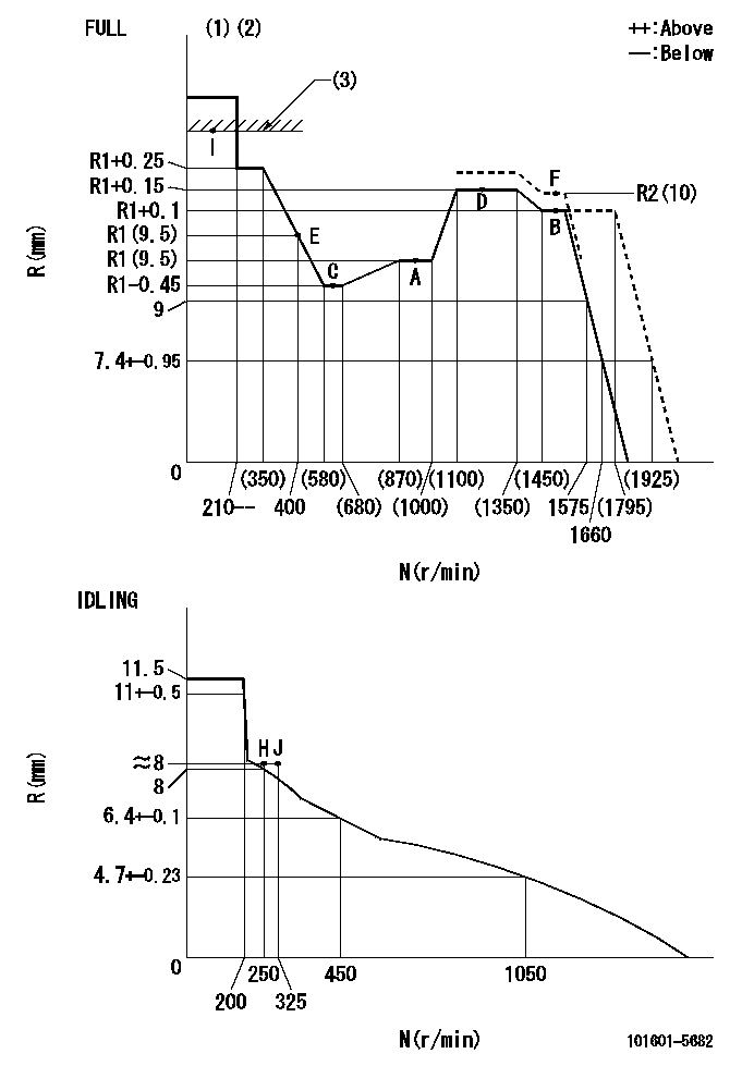
N:Pump speed
R:Rack position (mm)
(1)Torque cam stamping: T1
(2)Tolerance for racks not indicated: +-0.05mm.
(3)RACK LIMIT
----------
T1=C10
----------
----------
T1=C10
----------
Speed control lever angle

F:Full speed
I:Idle
(1)Stopper bolt set position 'H'
----------
----------
a=32deg+-3deg b=34deg+-5deg
----------
----------
a=32deg+-3deg b=34deg+-5deg
Stop lever angle
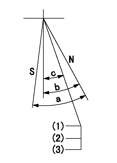
N:Pump normal
S:Stop the pump.
(1)Stopper bolt setting
(2)(Apply red paint after setting.)
(3)Engine normal
----------
----------
a=40deg+-5deg b=40deg+-5deg c=35deg+-2deg
----------
----------
a=40deg+-5deg b=40deg+-5deg c=35deg+-2deg
0000001501 TAMPER PROOF
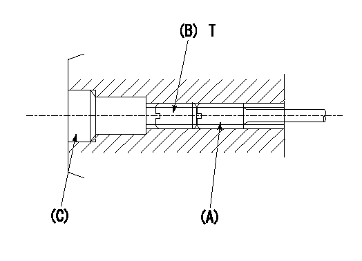
1. Method for setting tamperproof proofing
(1)After governor adjustment (torque cam phase adjustment), move the load lever to increase the full rack position to Ra.
(2)At pump speed N1, push in the screw (A) until the rack position is Rb.
(3)Temporarily caulk using the tip of a screwdriver
(4)Confirm that the rack at that time is at Rc.
(5)Lock using setscrew (B). (Tightening torque = T)
(6)Next, coat (C) with adhesive and then pressfit.
(7)Then, readjust the full rack position using the load lever.
----------
N1=1500r/min Ra=(0.4)mm Rb=R2(10)mm Rc=R2(10)mm
----------
T=4.9~7N-m(0.5~0.7Kgf-m)
----------
N1=1500r/min Ra=(0.4)mm Rb=R2(10)mm Rc=R2(10)mm
----------
T=4.9~7N-m(0.5~0.7Kgf-m)
Timing setting

(1)Pump vertical direction
(2)Position of gear's standard threaded hole at No 1 cylinder's beginning of injection
(3)-
(4)-
----------
----------
a=(70deg)
----------
----------
a=(70deg)
Information:
Engine Performance
Poor vessel performance is traditionally believed to be the result of a lack (or loss) of engine performance, when in fact the engine is only one of numerous factors that influence the overall performance of a vessel. Several factors determine the power demand on an engine. The engine has no control over the demand made upon it by the vessel design, such as hull, prop and driveline design. These same factors also affect the amount of power available to perform additional work such as to drive auxiliary pumps.If you feel you have a vessel performance problem, first consider the impact of vessel design and condition, loads, propeller and driveline condition, etc. on power demand. Deterioration of vessel systems (cooling, air intake and exhaust, fuel tanks, etc.) can only lessen the engine's chance to produce power and vessel speed. In the case of poor fuel economy, the engine is not likely to be the cause without the presence of excessive exhaust smoke and/or a significant loss of power.If you feel you have a valid engine performance problem, contact an authorized Caterpillar marine engine servicing dealer for assistance. If your engine is under warranty then the Caterpillar warranty will cover the cost of resolving a valid engine performance deficiency. However, if the engine is not found at fault, all costs incurred will be the responsibility of the owner. Adjustment of the fuel system outside Caterpillar specified limits will not improve fuel efficiency and could result in damage to the engine.Your Caterpillar dealer can determine engine condition and check the engine's external systems using a diagnostic procedure called the Marine Engine Performance Analysis Report (PAR). (See next topic).Caterpillar engines are designed and manufactured using state-of-the-art technology to provide maximum fuel efficiency and performance in all applications. To insure optimum performance for the life of your engine, follow the recommended operation and preventive maintenance procedures described in this publication.Marine Engine Performance Analysis Report (PAR)
Today's marine user is concerned with performance, cost of operation and satisfactory engine life. Traditionally, vessel performance has been directly related to the propulsion engine, when in fact the engine is only one of numerous factors influencing the propulsion system.To verify the condition of the propulsion system, Caterpillar has developed the Marine Engine Performance Analysis Report (PAR) program. Marine Engine PAR is an in-vessel test procedure, performed and evaluated by Caterpillar certified Marine Analysts under normal or bollard operating conditions, comparing the performance of all marine engine systems to original factory test cell specifications.When Marine Engine PAR testing is conducted at Sea Trial, it can assure you of a quality installation that confirms hull, rudders, propeller, marine transmission, ventilation and cooling systems are all properly matched for optimum performance and fuel efficiency.Caterpillar additionally recommends regularly scheduled (see Maintenance Schedule) Marine Engine PAR analyses to maintain optimum performance. Periodic PAR analyses can define propulsion system deterioration and aid in fine tuning the maintenance, repair and overhaul schedules, which will provide you the most economical and efficient cost of operation.
Have questions with 101601-5682?
Group cross 101601-5682 ZEXEL
Hino
Hino
101601-5682
9 400 611 429
220006451B
INJECTION-PUMP ASSEMBLY
W06E
W06E