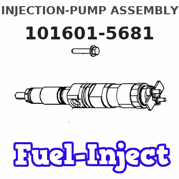
Information injection-pump assembly
ZEXEL
101601-5681
1016015681
Rating:
Service parts 101601-5681 INJECTION-PUMP ASSEMBLY:
1.
_
6.
COUPLING PLATE
7.
COUPLING PLATE
8.
_
9.
_
11.
Nozzle and Holder
23600-1593A
12.
Open Pre:MPa(Kqf/cm2)
21.6{220}

15.
NOZZLE SET
Cross reference number
ZEXEL
101601-5681
1016015681
Zexel num
Bosch num
Firm num
Name
101601-5681
INJECTION-PUMP ASSEMBLY
14BE PE6A PE
14BE PE6A PE
Calibration Data:
Adjustment conditions
Test oil
1404 Test oil ISO4113 or {SAEJ967d}
1404 Test oil ISO4113 or {SAEJ967d}
Test oil temperature
degC
40
40
45
Nozzle and nozzle holder
105780-8140
Bosch type code
EF8511/9A
Nozzle
105780-0000
Bosch type code
DN12SD12T
Nozzle holder
105780-2080
Bosch type code
EF8511/9
Opening pressure
MPa
17.2
Opening pressure
kgf/cm2
175
Injection pipe
Outer diameter - inner diameter - length (mm) mm 6-2-600
Outer diameter - inner diameter - length (mm) mm 6-2-600
Overflow valve
131424-5720
Overflow valve opening pressure
kPa
255
221
289
Overflow valve opening pressure
kgf/cm2
2.6
2.25
2.95
Tester oil delivery pressure
kPa
157
157
157
Tester oil delivery pressure
kgf/cm2
1.6
1.6
1.6
Direction of rotation (viewed from drive side)
Right R
Right R
Injection timing adjustment
Direction of rotation (viewed from drive side)
Right R
Right R
Injection order
1-4-2-6-
3-5
Pre-stroke
mm
3.1
3.07
3.13
Beginning of injection position
Drive side NO.1
Drive side NO.1
Difference between angles 1
Cal 1-4 deg. 60 59.75 60.25
Cal 1-4 deg. 60 59.75 60.25
Difference between angles 2
Cyl.1-2 deg. 120 119.75 120.25
Cyl.1-2 deg. 120 119.75 120.25
Difference between angles 3
Cal 1-6 deg. 180 179.75 180.25
Cal 1-6 deg. 180 179.75 180.25
Difference between angles 4
Cal 1-3 deg. 240 239.75 240.25
Cal 1-3 deg. 240 239.75 240.25
Difference between angles 5
Cal 1-5 deg. 300 299.75 300.25
Cal 1-5 deg. 300 299.75 300.25
Injection quantity adjustment
Adjusting point
-
Rack position
9.5
Pump speed
r/min
900
900
900
Average injection quantity
mm3/st.
60.2
58.2
62.2
Max. variation between cylinders
%
0
-3.5
3.5
Basic
*
Fixing the rack
*
Standard for adjustment of the maximum variation between cylinders
*
Injection quantity adjustment_02
Adjusting point
H
Rack position
8+-0.5
Pump speed
r/min
250
250
250
Average injection quantity
mm3/st.
6.8
5.3
8.3
Max. variation between cylinders
%
0
-10
10
Fixing the rack
*
Standard for adjustment of the maximum variation between cylinders
*
Injection quantity adjustment_03
Adjusting point
A
Rack position
R1(9.5)
Pump speed
r/min
900
900
900
Average injection quantity
mm3/st.
60.2
59.2
61.2
Basic
*
Fixing the lever
*
Injection quantity adjustment_04
Adjusting point
B
Rack position
R1+0.1
Pump speed
r/min
1500
1500
1500
Average injection quantity
mm3/st.
67.3
63.3
71.3
Fixing the lever
*
Injection quantity adjustment_05
Adjusting point
C
Rack position
R1-0.45
Pump speed
r/min
600
600
600
Average injection quantity
mm3/st.
37.9
33.9
41.9
Fixing the lever
*
Injection quantity adjustment_06
Adjusting point
D
Rack position
R1+0.15
Pump speed
r/min
1200
1200
1200
Average injection quantity
mm3/st.
67.8
63.8
71.8
Fixing the lever
*
Injection quantity adjustment_07
Adjusting point
E
Rack position
R1(9.5)
Pump speed
r/min
400
400
400
Average injection quantity
mm3/st.
32.9
28.9
36.9
Fixing the lever
*
Injection quantity adjustment_08
Adjusting point
I
Rack position
-
Pump speed
r/min
100
100
100
Average injection quantity
mm3/st.
99
99
109
Fixing the lever
*
Rack limit
*
Timer adjustment
Pump speed
r/min
1000+50
Advance angle
deg.
0
0
0
Remarks
Start
Start
Timer adjustment_02
Pump speed
r/min
1500
Advance angle
deg.
3.5
3.2
3.8
Remarks
Finish
Finish
Test data Ex:
Governor adjustment
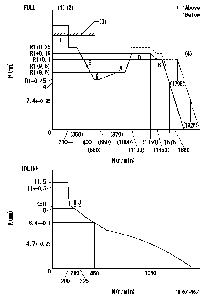
N:Pump speed
R:Rack position (mm)
(1)Torque cam stamping: T1
(2)Tolerance for racks not indicated: +-0.05mm.
(3)RACK LIMIT
(4)R2 (actual measurement)
----------
T1=C10
----------
----------
T1=C10
----------
Speed control lever angle

F:Full speed
I:Idle
(1)Stopper bolt set position 'H'
----------
----------
a=32deg+-3deg b=34deg+-5deg
----------
----------
a=32deg+-3deg b=34deg+-5deg
Stop lever angle
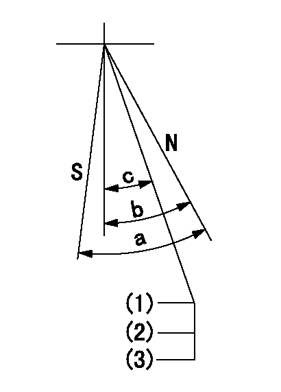
N:Pump normal
S:Stop the pump.
(1)Stopper bolt setting
(2)After setting, apply red paint.
(3)Engine normal
----------
----------
a=40deg+-5deg b=40deg+-5deg c=35deg+-2deg
----------
----------
a=40deg+-5deg b=40deg+-5deg c=35deg+-2deg
0000001501 TAMPER PROOF
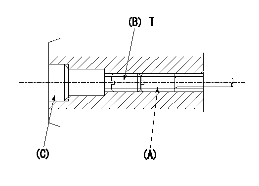
1. Method for setting tamperproof proofing
(1)After governor adjustment (torque cam phase adjustment), move the load lever to increase the full rack position to Ra.
(2)At pump speed N1, push in the screw (A) until the rack position is Rb.
(3)Temporarily caulk using the tip of a screwdriver
(4)Confirm that the rack at that time is at Rc.
(5)Lock using setscrew (B). (Tightening torque = T)
(6)Next, coat (C) with adhesive and then pressfit.
(7)Then, readjust the full rack position using the load lever.
----------
N1=1500r/min Ra=(0.4)mm Rb=R2 Rc=R2
----------
T=3.4~4.9N-m(0.35~0.5Kgf-m)
----------
N1=1500r/min Ra=(0.4)mm Rb=R2 Rc=R2
----------
T=3.4~4.9N-m(0.35~0.5Kgf-m)
Timing setting

(1)Pump vertical direction
(2)Position of gear's standard threaded hole at No 1 cylinder's beginning of injection
(3)-
(4)-
----------
----------
a=(70deg)
----------
----------
a=(70deg)
Information:
Stopping the engine immediately after it has been working under load can result in overheating and accelerated wear of the engine components. Follow the stopping procedures, outlined below, to allow the engine to cool. Excessive temperatures in the turbocharger center housing will cause oil coking problems.
Prior to stopping an engine that is being operated at low loads, run the engine at LOW IDLE for 30 seconds before stopping. If the engine is being operated at high load, then it should be run at LOW IDLE for five minutes to reduce and stabilize internal engine coolant and oil temperatures before stopping.Make sure the Engine Stopping procedure is understood. The engine may be shutdown in several ways. To manually stop the engine, refer to the following information and instructions.Emergency Stop Procedure
The Emergency Stop Pushbutton (ESPB) and Emergency stop controls are for EMERGENCY use ONLY. DO NOT use for normal stopping procedure. Emergency Stop controls should only be used when an emergency exists, and not used to routinely stop the engine. Do NOT start the engine until the problem necessitating the emergency stop has been located and corrected.
* Emergency stops may be made through the Emergency Stop Pushbutton (ESPB). If the need for emergency engine shutdown occurs, push the EMERGENCY STOP Pushbutton located on the control panel or the engine junction box. This will activate the air and/or fuel shutoffs. Reset the EMERGENCY STOP Pushbutton (pull out and rotate the button in the direction indicated on the button). Some EMERGENCY STOP Pushbuttons can be pulled out to reset, not requiring any rotation.Manual Stop Procedure
1. Reduce the engine speed to LOW IDLE. Shift the marine transmission to NEUTRAL and secure the vessel.2. Increase engine speed to no more than half engine speed for five minutes to cool the engine. Reduce engine speed to LOW IDLE. 3. Check the crankcase oil level while the engine is idling. Maintain the oil level between the ADD and FULL marks on the CHECK WITH ENGINE RUNNING or ENGINE AT LOW IDLE WITH OIL WARM side of the dipstick.4. Shift the marine transmission to FORWARD or REVERSE. Check the marine transmission oil level at ENGINE AT LOW IDLE WITH OIL WARM. Maintain oil level between the ADD and FULL marks on the dipstick. Shift the marine transmission back to NEUTRAL.5. The engine may be stopped by using one of the following engine mounted controls.Toggle Switch
Move OEM or customer supplied toggle switch to the OFF position to shut off the fuel shutoff solenoid.Manual Fuel Shutoff Lever (All Engines)
Do not use the emergency shutoff control for a normal stopping procedure. A manual shutdown shaft is provided to override the governor solenoid. This shutdown will only move the fuel control linkage to the fuel OFF position to starve the engine of fuel. It does not shut off the air inlet. The engine will coast to a stop. Be sure to secure any external system components that have been operating to support the engine operation.After Stopping the Engine
1. If freezing temperatures
Have questions with 101601-5681?
Group cross 101601-5681 ZEXEL
Hino
101601-5681
INJECTION-PUMP ASSEMBLY