Information injection-pump assembly
ZEXEL
101601-5660
1016015660
HINO
220006430A
220006430a
Rating:
Cross reference number
ZEXEL
101601-5660
1016015660
HINO
220006430A
220006430a
Zexel num
Bosch num
Firm num
Name
Calibration Data:
Adjustment conditions
Test oil
1404 Test oil ISO4113 or {SAEJ967d}
1404 Test oil ISO4113 or {SAEJ967d}
Test oil temperature
degC
40
40
45
Nozzle and nozzle holder
105780-8210
Nozzle
105780-0070
Bosch type code
DN12SD12T-1
Nozzle holder
105780-2080
Bosch type code
EF8511/9
Opening pressure
MPa
17.2
Opening pressure
kgf/cm2
175
Injection pipe
Outer diameter - inner diameter - length (mm) mm 6-2-600
Outer diameter - inner diameter - length (mm) mm 6-2-600
Overflow valve
134424-0920
Overflow valve opening pressure
kPa
162
147
177
Overflow valve opening pressure
kgf/cm2
1.65
1.5
1.8
Tester oil delivery pressure
kPa
157
157
157
Tester oil delivery pressure
kgf/cm2
1.6
1.6
1.6
Direction of rotation (viewed from drive side)
Right R
Right R
Injection timing adjustment
Direction of rotation (viewed from drive side)
Right R
Right R
Injection order
1-4-2-6-
3-5
Pre-stroke
mm
3.8
3.77
3.83
Beginning of injection position
Drive side NO.1
Drive side NO.1
Difference between angles 1
Cal 1-4 deg. 60 59.75 60.25
Cal 1-4 deg. 60 59.75 60.25
Difference between angles 2
Cyl.1-2 deg. 120 119.75 120.25
Cyl.1-2 deg. 120 119.75 120.25
Difference between angles 3
Cal 1-6 deg. 180 179.75 180.25
Cal 1-6 deg. 180 179.75 180.25
Difference between angles 4
Cal 1-3 deg. 240 239.75 240.25
Cal 1-3 deg. 240 239.75 240.25
Difference between angles 5
Cal 1-5 deg. 300 299.75 300.25
Cal 1-5 deg. 300 299.75 300.25
Injection quantity adjustment
Adjusting point
-
Rack position
11.5
Pump speed
r/min
850
850
850
Average injection quantity
mm3/st.
77.6
76
79.2
Max. variation between cylinders
%
0
-3.5
3.5
Basic
*
Fixing the rack
*
Standard for adjustment of the maximum variation between cylinders
*
Injection quantity adjustment_02
Adjusting point
H
Rack position
9+-0.5
Pump speed
r/min
250
250
250
Each cylinder's injection qty
mm3/st.
16.9
15.9
17.9
Fixing the rack
*
Standard for adjustment of the maximum variation between cylinders
*
Injection quantity adjustment_03
Adjusting point
A
Rack position
R1(11.5)
Pump speed
r/min
850
850
850
Average injection quantity
mm3/st.
77.6
76.6
78.6
Basic
*
Fixing the lever
*
Injection quantity adjustment_04
Adjusting point
B
Rack position
R1+0.5
Pump speed
r/min
1450
1450
1450
Average injection quantity
mm3/st.
88.9
84.9
92.9
Fixing the lever
*
Injection quantity adjustment_05
Adjusting point
C
Rack position
R1-0.3
Pump speed
r/min
600
600
600
Average injection quantity
mm3/st.
64.2
60.2
68.2
Fixing the lever
*
Injection quantity adjustment_06
Adjusting point
D
Rack position
R1+0.5
Pump speed
r/min
1150
1150
1150
Average injection quantity
mm3/st.
87.4
83.4
91.4
Fixing the lever
*
Injection quantity adjustment_07
Adjusting point
I
Rack position
-
Pump speed
r/min
100
100
100
Average injection quantity
mm3/st.
140
140
150
Fixing the lever
*
Rack limit
*
Timer adjustment
Pump speed
r/min
925--
Advance angle
deg.
0
0
0
Load
1/4
Remarks
Start
Start
Timer adjustment_02
Pump speed
r/min
875
Advance angle
deg.
0.3
Load
1/4
Timer adjustment_03
Pump speed
r/min
(920--)
Advance angle
deg.
1
0.7
1.3
Load
4/4
Timer adjustment_04
Pump speed
r/min
1175+50
Advance angle
deg.
1
0.7
1.3
Load
3/4
Timer adjustment_05
Pump speed
r/min
1400+50
Advance angle
deg.
5.5
5.2
5.8
Load
4/4
Remarks
Finish
Finish
Test data Ex:
Governor adjustment
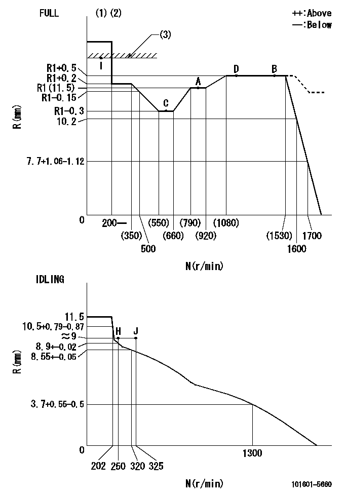
N:Pump speed
R:Rack position (mm)
(1)Torque cam stamping: T1
(2)Tolerance for racks not indicated: +-0.05mm.
(3)RACK LIMIT
----------
T1=F80
----------
----------
T1=F80
----------
Speed control lever angle
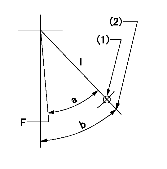
F:Full speed
I:Idle
(1)Use the hole at R = aa
(2)Stopper bolt set position 'H'
----------
aa=55mm
----------
a=37deg+-3deg b=40deg+-5deg
----------
aa=55mm
----------
a=37deg+-3deg b=40deg+-5deg
Stop lever angle
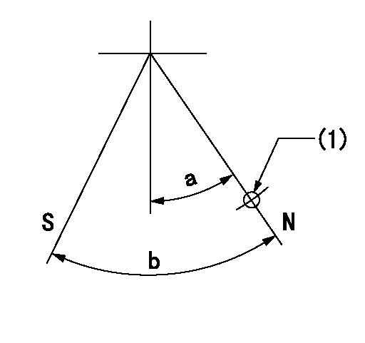
N:Pump normal
S:Stop the pump.
(1)Use the hole at R = aa
----------
aa=35mm
----------
a=14.5deg+-5deg b=40deg+-5deg
----------
aa=35mm
----------
a=14.5deg+-5deg b=40deg+-5deg
0000001501 AIR CYLINDER

(A): Speed lever
(B): Set bolt
(C): air cylinder
(D): nut
(E): fix
1. Air cylinder adjustment procedure
(1)With the speed lever in the idling position, temporarily set the clearance between speed lever (A) and set bolt (B) at approximately L1.
(2)Set the speed to N1 and supply positive pressure P1 to the air cylinder (C).
(3)Gradually push set bolt (B) out (approximately L2) and tighten nut (D) where the speed is N2 and the rack position is Ra.
(4)Apply positive pressure P1 several times.
(5)Confirm that the lever returns to the idle position at positive pressure P2.
(6)Also, confirm that the rack position is Rb at air pressure P1.
----------
L=0.6++mm L1=5mm L2=- Ra=8.8+-0.1mm Rb=8.8+-0.1mm N1=475r/min N2=475r/min P1=392+98kPa(4+1kgf/cm2) P2=0kPa(0kgf/cm2)
----------
----------
L=0.6++mm L1=5mm L2=- Ra=8.8+-0.1mm Rb=8.8+-0.1mm N1=475r/min N2=475r/min P1=392+98kPa(4+1kgf/cm2) P2=0kPa(0kgf/cm2)
----------
Timing setting

(1)Pump vertical direction
(2)Coupling's key groove position at No 1 cylinder's beginning of injection
(3)-
(4)-
----------
----------
a=(50deg)
----------
----------
a=(50deg)
Information:
Most commercial antifreezes are formulated for gasoline engine applications and will, therefore, have high silicate content. ASTM D4985 antifreeze is a low silicate antifreeze and should be used if not using Caterpillar Antifreeze. The percentage of antifreeze and water should be determined by the amount of freeze protection required. Follow the instructions provided by the antifreeze supplier.When using any antifreeze (except Caterpillar Antifreeze) supplemental coolant additive is required at initial fill. Caterpillar or other manufacturer's products can be used as the supplemental coolant additive.Add 1 liter (1 U.S. quart) of liquid supplemental coolant additive for every 15 liter (4 U.S. gallon) so that the cooling system will have a three to six percent concentration of supplemental coolant additive.DO NOT mix Caterpillar Supplemental Coolant Additive (Conditioner) or supplemental coolant additive elements with the other products available; select a cooling system treatment and use it exclusively. If other than Caterpillar products are used as the supplemental coolant additive, follow the manufacturers' recommendation for cooling system treatment and test evaluation.Supplemental Coolant Additive (Conditioner or Inhibitor)
Never use coolant in Caterpillar engines without supplemental coolant additive regardless of antifreeze concentration.Caterpillar or other manufacturer's products can be used as the supplemental coolant additive. DO NOT mix Caterpillar Supplemental Coolant Additive (Conditioner) liquid or elements with the other commercial products available; select a cooling system treatment and use it exclusively.Excessive concentration of supplemental coolant additive can form deposits which may cause engine damage, reduce the engine's heat transfer characteristics and could also accelerate water pump seal wear.
The cooling system MUST contain supplemental coolant additives (conditioner or inhibitor) to control corrosion, cavitation and deposits. It is also necessary to prevent rust, scale, pitting and/or corrosion of engine parts contacted by coolant. The cooling system should be protected with a minimum of three percent concentration at all times, regardless of the concentration of antifreeze. Use supplemental coolant additive liquid OR an element (if equipped) to maintain a three to six percent concentration in the cooling system.Use the 8T5296 Test Kit to check and monitor the SCA concentration for antifreeze/water coolant mixture. The Caterpillar 8T5296 Test Kit checks for concentration of nitrates in the coolant solution. Some other manufacturers' supplemental coolant additive (SCA) are phosphate based and the 8T5296 Test Kit will NOT provide accurate results. Caterpillar recommends that their test kit be used to check coolant solution concentration.If other than Caterpillar products are used as the supplemental coolant additive, follow the manufacturers' recommendation for cooling system treatment and test evaluation. Commercial supplemental coolant additive products must contain silicates and a minimum of 70 gr/U.S. gallon (1200 ppm) nitrites.Caterpillar liquid supplemental coolant additive (Conditioner) is available through your Caterpillar dealer in quantities that follow. Pre-chargeCaterpillar Antifreeze DOES NOT require supplemental coolant additive added at initial fill, however additive is required on a maintenance basis. For engines equipped with supplemental coolant additive elements, the last MAINTENANCE element should not be replaced at FLUSH & FILL or Overhaul until the next oil change interval. Corrosion in raw (sea) water