Information injection-pump assembly
ZEXEL
101601-5590
1016015590
Rating:
Service parts 101601-5590 INJECTION-PUMP ASSEMBLY:
1.
_
6.
COUPLING PLATE
7.
COUPLING PLATE
8.
_
9.
_
11.
Nozzle and Holder
23600-2060A
12.
Open Pre:MPa(Kqf/cm2)
21.6{220}
15.
NOZZLE SET
Cross reference number
ZEXEL
101601-5590
1016015590
Zexel num
Bosch num
Firm num
Name
101601-5590
INJECTION-PUMP ASSEMBLY
Calibration Data:
Adjustment conditions
Test oil
1404 Test oil ISO4113 or {SAEJ967d}
1404 Test oil ISO4113 or {SAEJ967d}
Test oil temperature
degC
40
40
45
Nozzle and nozzle holder
105780-8140
Bosch type code
EF8511/9A
Nozzle
105780-0000
Bosch type code
DN12SD12T
Nozzle holder
105780-2080
Bosch type code
EF8511/9
Opening pressure
MPa
17.2
Opening pressure
kgf/cm2
175
Injection pipe
Outer diameter - inner diameter - length (mm) mm 6-2-600
Outer diameter - inner diameter - length (mm) mm 6-2-600
Overflow valve
131424-5720
Overflow valve opening pressure
kPa
255
221
289
Overflow valve opening pressure
kgf/cm2
2.6
2.25
2.95
Tester oil delivery pressure
kPa
157
157
157
Tester oil delivery pressure
kgf/cm2
1.6
1.6
1.6
Direction of rotation (viewed from drive side)
Right R
Right R
Injection timing adjustment
Direction of rotation (viewed from drive side)
Right R
Right R
Injection order
1-4-2-6-
3-5
Pre-stroke
mm
3.1
3.07
3.13
Beginning of injection position
Drive side NO.1
Drive side NO.1
Difference between angles 1
Cal 1-4 deg. 60 59.75 60.25
Cal 1-4 deg. 60 59.75 60.25
Difference between angles 2
Cyl.1-2 deg. 120 119.75 120.25
Cyl.1-2 deg. 120 119.75 120.25
Difference between angles 3
Cal 1-6 deg. 180 179.75 180.25
Cal 1-6 deg. 180 179.75 180.25
Difference between angles 4
Cal 1-3 deg. 240 239.75 240.25
Cal 1-3 deg. 240 239.75 240.25
Difference between angles 5
Cal 1-5 deg. 300 299.75 300.25
Cal 1-5 deg. 300 299.75 300.25
Injection quantity adjustment
Adjusting point
-
Rack position
9.1
Pump speed
r/min
900
900
900
Average injection quantity
mm3/st.
48.9
46.9
50.9
Max. variation between cylinders
%
0
-3.5
3.5
Basic
*
Fixing the rack
*
Standard for adjustment of the maximum variation between cylinders
*
Injection quantity adjustment_02
Adjusting point
H
Rack position
8+-0.5
Pump speed
r/min
250
250
250
Average injection quantity
mm3/st.
7
5.5
8.5
Max. variation between cylinders
%
0
-10
10
Fixing the rack
*
Standard for adjustment of the maximum variation between cylinders
*
Injection quantity adjustment_03
Adjusting point
A
Rack position
R1(9.1)
Pump speed
r/min
900
900
900
Average injection quantity
mm3/st.
48.9
47.9
49.9
Basic
*
Fixing the lever
*
Injection quantity adjustment_04
Adjusting point
B
Rack position
R1-0.1
Pump speed
r/min
1500
1500
1500
Average injection quantity
mm3/st.
51.3
47.3
55.3
Fixing the lever
*
Injection quantity adjustment_05
Adjusting point
C
Rack position
R1-0.25
Pump speed
r/min
600
600
600
Average injection quantity
mm3/st.
35.9
31.9
39.9
Fixing the lever
*
Injection quantity adjustment_06
Adjusting point
D
Rack position
R1(9.1)
Pump speed
r/min
1200
1200
1200
Average injection quantity
mm3/st.
52.1
48.1
56.1
Fixing the lever
*
Injection quantity adjustment_07
Adjusting point
E
Rack position
(R1+0.45
)
Pump speed
r/min
400
400
400
Average injection quantity
mm3/st.
31.4
27.4
35.4
Fixing the lever
*
Injection quantity adjustment_08
Adjusting point
I
Rack position
-
Pump speed
r/min
100
100
100
Average injection quantity
mm3/st.
111
101
121
Fixing the lever
*
Rack limit
*
Timer adjustment
Pump speed
r/min
1330--
Advance angle
deg.
0
0
0
Load
3/4
Remarks
Start
Start
Timer adjustment_02
Pump speed
r/min
1280
Advance angle
deg.
0.3
Load
3/4
Timer adjustment_03
Pump speed
r/min
1500
Advance angle
deg.
4.5
4.2
4.8
Load
4/4
Remarks
Finish
Finish
Test data Ex:
Governor adjustment
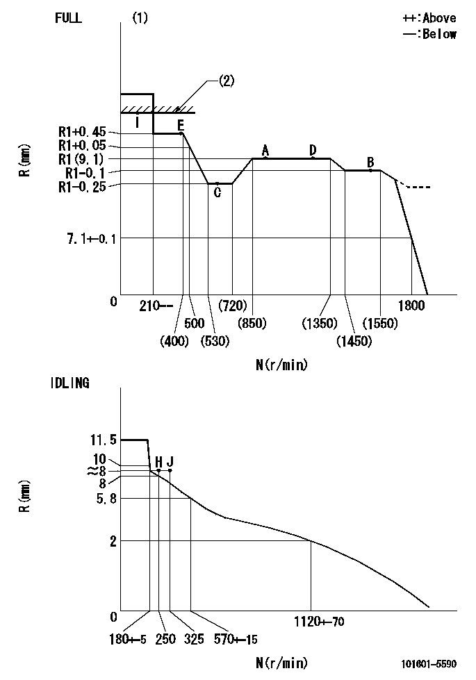
N:Pump speed
R:Rack position (mm)
(1)Torque cam stamping: T1
(2)RACK LIMIT
----------
T1=E05
----------
----------
T1=E05
----------
Speed control lever angle
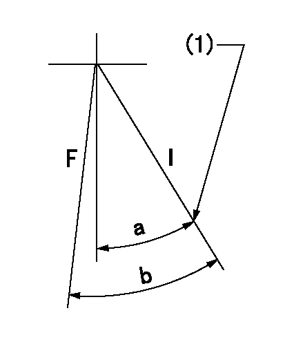
F:Full speed
I:Idle
(1)Stopper bolt set position 'H'
----------
----------
a=46deg+-5deg b=(49deg)+-3deg
----------
----------
a=46deg+-5deg b=(49deg)+-3deg
Stop lever angle
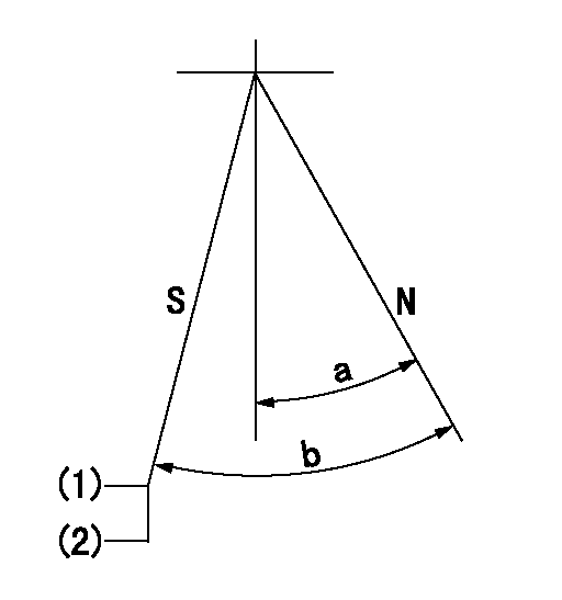
N:Engine normal (pump normal)
S:Engine stop
(1)Set the stopper screw.
(2)(Apply red paint after setting.)
----------
----------
a=20deg+-5deg b=(30.5deg)+-5deg
----------
----------
a=20deg+-5deg b=(30.5deg)+-5deg
0000001501 LEVER
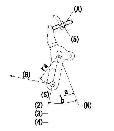
(N) Engine normal (pump normal)
(S) Engine stop
(A) stopper screw
(B) Stop direction (perpendicular)
Stop lever adjusting procedure
(1)After completing adjustment, confirm that the engine's normal lever angle (pump's normal lever) is within the specifications in the figure above.
(2)With the speed lever at Full and the pump speed at Na (specified speed), temporarily set the stopper screw (A) at the rack position Ra.
(3)Turn the stopper screw (A) Rb in the stop direction (Nb turns) and set it. Measure the rack position. (Rack position = approx. Rc)
(4)After setting, confirm non-injection with the speed lever at idle and pump speed at Nc.
(5)After adjustment, apply red paint.
----------
Na=1750r/min Ra=4.9mm Rb=1.5mm Nb=1.5 Rc=2.9mm Nc=250r/min
----------
ra=37mm a=20deg+-5deg b=(30.5deg)+-5deg
----------
Na=1750r/min Ra=4.9mm Rb=1.5mm Nb=1.5 Rc=2.9mm Nc=250r/min
----------
ra=37mm a=20deg+-5deg b=(30.5deg)+-5deg
Timing setting

(1)Pump vertical direction
(2)Position of gear's standard threaded hole at No 1 cylinder's beginning of injection
(3)-
(4)-
----------
----------
a=(70deg)
----------
----------
a=(70deg)
Information:
Voltage Regulator and Generator
Clean and Inspect
Before working inside the generator, make sure that the starter motor can not be activated by any automatic or manual signal.When the engine-generator is operating, voltages up to 600V are present in these areas near or on the regulator:1. The regulator terminal strip2. The excitation transformer terminal strip (self-excited generator only).Do not short these terminals to ground with any part of the body or any conductive material. Loss of life or injury could result from electrical shock or injury from molten metal.An electrical shock can be received from the regulator capacitor (C1) when the engine-generator is not in operation. To avoid possible injury, discharge the stored charge using an 100 ohm resistor across C1 terminals.
Electronic components in the regulator can be damaged during generator operation if contact is made between the part and ground.
If Moisture is allowed to remain in contact with an electrical winding, some of the moisture will eventually be absorbed. This will lower the resistance of the winding insulation. The insulation used on the windings of Caterpillar generators is moisture resistant, but constant exposure to moisture will gradually lower the insulation's resistance.Dirt can make the problem worse because it can hold the moisture in contact with the insulation. Salt (from sea air) can also make the problem much worse. This is because salt tends to absorb moisture from the air. When the salt and moisture combine, they make a good electrical conductor.Clean the voltage regulator and generator of dirt and debris. Use a brush to loosen accumulations of dirt and a vacuum system for removal. Use of compressed air is not recommended, because of moisture present in the form of condensate.Carbon tracking on insulators can be caused by dirt or loose connections. These carbon paths must be cleaned or the insulators replaced. Failure to correct a carbon tracking problem will eventually result in a short in the electrical circuit.Visually check for loose or broken wires and connections. Check the wires and connections on the regulator assembly. Check that all circuit boards are fully plugged in their sockets. Check all wires and connections in the generator. Make any necessary repairs to the wiring as required. Refer to the "Electric Set Generator Service Manual" for testing and adjusting or disassembly and assembly procedures.Space Heaters
The SR4 generator can operate in high humidity conditions without problems. However, problems can occur when the generator is idle and the surrounding air is warmer than the generator. Moisture can form on the windings and result in poor performance and even result in damage to the windings. Whenever the generator is not in use, insure that the space heaters are in operation.An external source of either 115 or 230 (200 v at 50 Hz) volts A.C. is required to operate the space heaters. Space Heater Connection to External Source H1, H2, H3, H4. Terminal Strip Terminals If 115 VAC source is available, connect
Have questions with 101601-5590?
Group cross 101601-5590 ZEXEL
Hino
Hino
101601-5590
INJECTION-PUMP ASSEMBLY