Information injection-pump assembly
BOSCH
9 400 614 620
9400614620
ZEXEL
101601-5581
1016015581
HINO
220006380A
220006380a
Rating:
Service parts 101601-5581 INJECTION-PUMP ASSEMBLY:
1.
_
6.
COUPLING PLATE
7.
COUPLING PLATE
8.
_
9.
_
11.
Nozzle and Holder
12.
Open Pre:MPa(Kqf/cm2)
21.6(220)
15.
NOZZLE SET
Cross reference number
BOSCH
9 400 614 620
9400614620
ZEXEL
101601-5581
1016015581
HINO
220006380A
220006380a
Zexel num
Bosch num
Firm num
Name
101601-5581
9 400 614 620
220006380A HINO
INJECTION-PUMP ASSEMBLY
W06E * K
W06E * K
Calibration Data:
Adjustment conditions
Test oil
1404 Test oil ISO4113 or {SAEJ967d}
1404 Test oil ISO4113 or {SAEJ967d}
Test oil temperature
degC
40
40
45
Nozzle and nozzle holder
105780-8140
Bosch type code
EF8511/9A
Nozzle
105780-0000
Bosch type code
DN12SD12T
Nozzle holder
105780-2080
Bosch type code
EF8511/9
Opening pressure
MPa
17.2
Opening pressure
kgf/cm2
175
Injection pipe
Outer diameter - inner diameter - length (mm) mm 6-2-600
Outer diameter - inner diameter - length (mm) mm 6-2-600
Overflow valve
131424-5720
Overflow valve opening pressure
kPa
255
221
289
Overflow valve opening pressure
kgf/cm2
2.6
2.25
2.95
Tester oil delivery pressure
kPa
157
157
157
Tester oil delivery pressure
kgf/cm2
1.6
1.6
1.6
Direction of rotation (viewed from drive side)
Right R
Right R
Injection timing adjustment
Direction of rotation (viewed from drive side)
Right R
Right R
Injection order
1-4-2-6-
3-5
Pre-stroke
mm
3.1
3.07
3.13
Beginning of injection position
Drive side NO.1
Drive side NO.1
Difference between angles 1
Cal 1-4 deg. 60 59.75 60.25
Cal 1-4 deg. 60 59.75 60.25
Difference between angles 2
Cyl.1-2 deg. 120 119.75 120.25
Cyl.1-2 deg. 120 119.75 120.25
Difference between angles 3
Cal 1-6 deg. 180 179.75 180.25
Cal 1-6 deg. 180 179.75 180.25
Difference between angles 4
Cal 1-3 deg. 240 239.75 240.25
Cal 1-3 deg. 240 239.75 240.25
Difference between angles 5
Cal 1-5 deg. 300 299.75 300.25
Cal 1-5 deg. 300 299.75 300.25
Injection quantity adjustment
Adjusting point
-
Rack position
9.4
Pump speed
r/min
900
900
900
Average injection quantity
mm3/st.
48.9
46.9
50.9
Max. variation between cylinders
%
0
-3.5
3.5
Basic
*
Fixing the rack
*
Standard for adjustment of the maximum variation between cylinders
*
Injection quantity adjustment_02
Adjusting point
H
Rack position
8.3+-0.5
Pump speed
r/min
250
250
250
Average injection quantity
mm3/st.
7
5.5
8.5
Max. variation between cylinders
%
0
-10
10
Fixing the rack
*
Standard for adjustment of the maximum variation between cylinders
*
Injection quantity adjustment_03
Adjusting point
A
Rack position
R1(9.4)
Pump speed
r/min
900
900
900
Average injection quantity
mm3/st.
48.9
47.9
49.9
Basic
*
Fixing the lever
*
Injection quantity adjustment_04
Adjusting point
B
Rack position
R1-0.1
Pump speed
r/min
1500
1500
1500
Average injection quantity
mm3/st.
51.3
47.3
55.3
Fixing the lever
*
Injection quantity adjustment_05
Adjusting point
C
Rack position
R1-0.25
Pump speed
r/min
600
600
600
Average injection quantity
mm3/st.
35.9
31.9
39.9
Fixing the lever
*
Injection quantity adjustment_06
Adjusting point
D
Rack position
R1(9.4)
Pump speed
r/min
1200
1200
1200
Average injection quantity
mm3/st.
52.1
48.1
56.1
Fixing the lever
*
Injection quantity adjustment_07
Adjusting point
E
Rack position
(R1+0.45
)
Pump speed
r/min
400
400
400
Average injection quantity
mm3/st.
31.4
27.4
35.4
Fixing the lever
*
Injection quantity adjustment_08
Adjusting point
I
Rack position
-
Pump speed
r/min
100
100
100
Average injection quantity
mm3/st.
111
101
121
Fixing the lever
*
Rack limit
*
Timer adjustment
Pump speed
r/min
1330--
Advance angle
deg.
0
0
0
Load
3/4
Remarks
Start
Start
Timer adjustment_02
Pump speed
r/min
1280
Advance angle
deg.
0.3
Load
3/4
Timer adjustment_03
Pump speed
r/min
1500
Advance angle
deg.
4.5
4.2
4.8
Load
4/4
Remarks
Finish
Finish
Test data Ex:
Governor adjustment
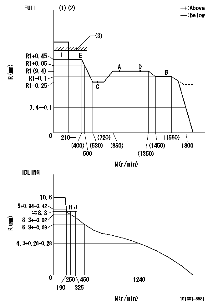
N:Pump speed
R:Rack position (mm)
(1)Torque cam stamping: T1
(2)Tolerance for racks not indicated: +-0.05mm.
(3)RACK LIMIT
----------
T1=E04
----------
----------
T1=E04
----------
Speed control lever angle
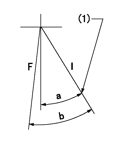
F:Full speed
I:Idle
(1)Stopper bolt set position 'H'
----------
----------
a=37deg+-5deg b=39deg+-3deg
----------
----------
a=37deg+-5deg b=39deg+-3deg
Stop lever angle
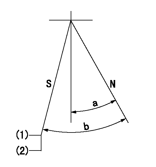
N:Engine normal (pump normal)
S:Engine stop
(1)Set the stopper screw.
(2)(Apply red paint after setting.)
----------
----------
a=20deg+-5deg b=29.5deg+-5deg
----------
----------
a=20deg+-5deg b=29.5deg+-5deg
0000001501 LEVER
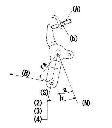
(N) Engine normal (pump normal)
(S) Engine stop
(A) stopper screw
(B) Stop direction (perpendicular)
Stop lever adjusting procedure
(1)After completing adjustment, confirm that the engine's normal lever angle (pump's normal lever) is within the specifications in the figure above.
(2)With the speed lever at Full and the pump speed at Na (specified speed), temporarily set the stopper screw (A) at the rack position Ra.
(3)Turn the stopper screw (A) Rb in the stop direction (Nb turns) and set it. Measure the rack position. (Rack position = approx. Rc)
(4)After setting, confirm non-injection with the speed lever at idle and pump speed at Nc.
(5)After adjustment, apply red paint.
----------
Na=1750r/min Ra=5.2mm Rb=1.5mm Nb=1.5 Rc=3.2mm Nc=250r/min
----------
ra=37mm a=20deg+-5deg b=29.5deg+-5deg
----------
Na=1750r/min Ra=5.2mm Rb=1.5mm Nb=1.5 Rc=3.2mm Nc=250r/min
----------
ra=37mm a=20deg+-5deg b=29.5deg+-5deg
Timing setting

(1)Pump vertical direction
(2)Position of gear's standard threaded hole at No 1 cylinder's beginning of injection
(3)-
(4)-
----------
----------
a=(70deg)
----------
----------
a=(70deg)
Information:
Storage Procedure
When a generator is in storage for any length of time, moisture condenses in the windings. Minimize the condensation by use of a dry storage space and space heaters. Refer to step 2 belowIf a brush-type generator (SRCR) is to be in storage for a year or more, lift the brushes off the slip ring to prevent damage to the slip ring by chemical action.After Storage
Test the main stator windings with a megohmmeter in the following situations: 1. Before initial startup of generator set.2. Every 3 months* if generator is operating in a humid environment.3. If generator has not been run under load for 3 months* or more.*This is a guideline only. It may be necessary to megger more frequently if environment is extremely humid, salty or if the last megger test was close to 1 megohm.The megohmmeter test is described in Service Manuals SENR2180 or SENR7968. A reading of 1 meghom or less indicates that the winding has absorbed too much moisture.To Remove Moisture
To remove moisture caused by high humidity, use one of the following methods to make the generator dry:1. Energize space heaters in generator if so equipped.2. Put the generator in an oven at a temperature of not more than 85°C (185°F) for four hours.
If an oven is used for drying, use a forced air type rather than a radiant type. Radiant ovens can cause localized overheating.
3. Space heaters of the same type used in marine applications, can be installed on generators. (See the Parts Book.) These heaters heat the windings to remove moisture and should be connected at all times in high humidity conditions whenever the generator is not running.4. Use a canvas enclosure around the generator and heating lamps to increase the temperature. Make an opening in the top for release of moisture.5. Send a low voltage current through the windings to increase the temperature of the windings. Do not exceed 85°C (185°F).If the megohmmeter test reads under 1 megohm after the drying or if it goes below 1 megohm shortly after drying, contact your Caterpillar dealer. The insulation has deteriorated and should be reconditioned.
Have questions with 101601-5581?
Group cross 101601-5581 ZEXEL
Hino
Hino
101601-5581
9 400 614 620
220006380A
INJECTION-PUMP ASSEMBLY
W06E
W06E