Information injection-pump assembly
ZEXEL
101601-5580
1016015580
Rating:
Service parts 101601-5580 INJECTION-PUMP ASSEMBLY:
1.
_
6.
COUPLING PLATE
7.
COUPLING PLATE
8.
_
9.
_
11.
Nozzle and Holder
23600-2060A
12.
Open Pre:MPa(Kqf/cm2)
21.6{220}
15.
NOZZLE SET
Cross reference number
ZEXEL
101601-5580
1016015580
Zexel num
Bosch num
Firm num
Name
101601-5580
INJECTION-PUMP ASSEMBLY
Calibration Data:
Adjustment conditions
Test oil
1404 Test oil ISO4113 or {SAEJ967d}
1404 Test oil ISO4113 or {SAEJ967d}
Test oil temperature
degC
40
40
45
Nozzle and nozzle holder
105780-8140
Bosch type code
EF8511/9A
Nozzle
105780-0000
Bosch type code
DN12SD12T
Nozzle holder
105780-2080
Bosch type code
EF8511/9
Opening pressure
MPa
17.2
Opening pressure
kgf/cm2
175
Injection pipe
Outer diameter - inner diameter - length (mm) mm 6-2-600
Outer diameter - inner diameter - length (mm) mm 6-2-600
Overflow valve
131424-5720
Overflow valve opening pressure
kPa
255
221
289
Overflow valve opening pressure
kgf/cm2
2.6
2.25
2.95
Tester oil delivery pressure
kPa
157
157
157
Tester oil delivery pressure
kgf/cm2
1.6
1.6
1.6
Direction of rotation (viewed from drive side)
Right R
Right R
Injection timing adjustment
Direction of rotation (viewed from drive side)
Right R
Right R
Injection order
1-4-2-6-
3-5
Pre-stroke
mm
3.1
3.07
3.13
Beginning of injection position
Drive side NO.1
Drive side NO.1
Difference between angles 1
Cal 1-4 deg. 60 59.75 60.25
Cal 1-4 deg. 60 59.75 60.25
Difference between angles 2
Cyl.1-2 deg. 120 119.75 120.25
Cyl.1-2 deg. 120 119.75 120.25
Difference between angles 3
Cal 1-6 deg. 180 179.75 180.25
Cal 1-6 deg. 180 179.75 180.25
Difference between angles 4
Cal 1-3 deg. 240 239.75 240.25
Cal 1-3 deg. 240 239.75 240.25
Difference between angles 5
Cal 1-5 deg. 300 299.75 300.25
Cal 1-5 deg. 300 299.75 300.25
Injection quantity adjustment
Adjusting point
-
Rack position
9.4
Pump speed
r/min
900
900
900
Average injection quantity
mm3/st.
48.9
46.9
50.9
Max. variation between cylinders
%
0
-3.5
3.5
Basic
*
Fixing the rack
*
Standard for adjustment of the maximum variation between cylinders
*
Injection quantity adjustment_02
Adjusting point
H
Rack position
8.3+-0.5
Pump speed
r/min
250
250
250
Average injection quantity
mm3/st.
7
5.5
8.5
Max. variation between cylinders
%
0
-10
10
Fixing the rack
*
Standard for adjustment of the maximum variation between cylinders
*
Injection quantity adjustment_03
Adjusting point
A
Rack position
R1(9.4)
Pump speed
r/min
900
900
900
Average injection quantity
mm3/st.
48.9
47.9
49.9
Basic
*
Fixing the lever
*
Injection quantity adjustment_04
Adjusting point
B
Rack position
R1-0.1
Pump speed
r/min
1500
1500
1500
Average injection quantity
mm3/st.
51.3
47.3
55.3
Fixing the lever
*
Injection quantity adjustment_05
Adjusting point
C
Rack position
R1-0.25
Pump speed
r/min
600
600
600
Average injection quantity
mm3/st.
35.9
31.9
39.9
Fixing the lever
*
Injection quantity adjustment_06
Adjusting point
D
Rack position
R1(9.4)
Pump speed
r/min
1200
1200
1200
Average injection quantity
mm3/st.
52.1
48.1
56.1
Fixing the lever
*
Injection quantity adjustment_07
Adjusting point
E
Rack position
(R1+0.45
)
Pump speed
r/min
400
400
400
Average injection quantity
mm3/st.
31.4
27.4
35.4
Fixing the lever
*
Injection quantity adjustment_08
Adjusting point
I
Rack position
-
Pump speed
r/min
100
100
100
Average injection quantity
mm3/st.
111
101
121
Fixing the lever
*
Rack limit
*
Timer adjustment
Pump speed
r/min
1330--
Advance angle
deg.
0
0
0
Load
3/4
Remarks
Start
Start
Timer adjustment_02
Pump speed
r/min
1280
Advance angle
deg.
0.3
Load
3/4
Timer adjustment_03
Pump speed
r/min
1500
Advance angle
deg.
4.5
4.2
4.8
Load
4/4
Remarks
Finish
Finish
Test data Ex:
Governor adjustment
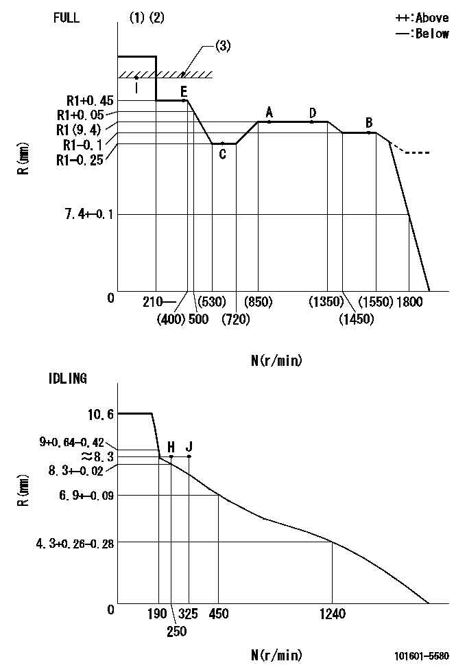
N:Pump speed
R:Rack position (mm)
(1)Torque cam stamping: T1
(2)Tolerance for racks not indicated: +-0.05mm.
(3)RACK LIMIT
----------
T1=E04
----------
----------
T1=E04
----------
Speed control lever angle

F:Full speed
I:Idle
(1)Stopper bolt setting
----------
----------
a=37deg+-5deg b=39deg+-3deg
----------
----------
a=37deg+-5deg b=39deg+-3deg
Stop lever angle
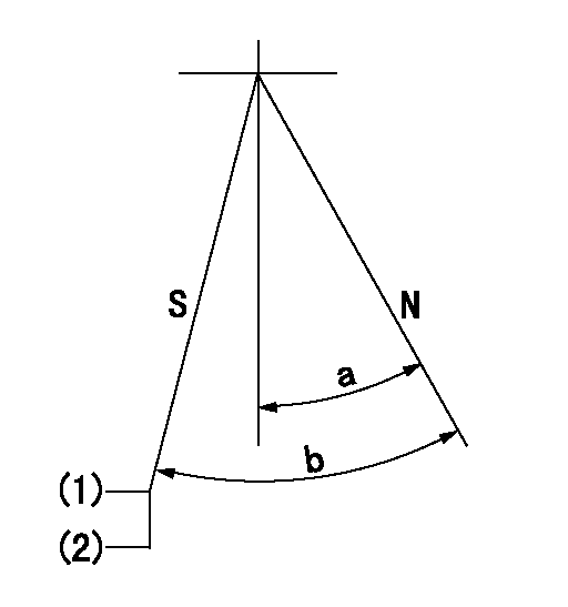
N:Engine normal (pump normal)
S:Engine stop
(1)At speed = aa, temporarily set the stopper screw so that the rack = bb.
(2)Further turn the stop screw cc (dd turns) in the stop direction and set (rack position = ee).
(3)After setting, apply red paint.
----------
aa=1750r/min bb=5.2mm cc=1.5mm dd=1.5 ee=(3.2)mm
----------
a=20deg+-5deg b=29.5deg+-5deg
----------
aa=1750r/min bb=5.2mm cc=1.5mm dd=1.5 ee=(3.2)mm
----------
a=20deg+-5deg b=29.5deg+-5deg
Timing setting

(1)Pump vertical direction
(2)Position of gear's standard threaded hole at No 1 cylinder's beginning of injection
(3)-
(4)-
----------
----------
a=(70deg)
----------
----------
a=(70deg)
Information:
Storage Procedure
1. Clean the outside of the engine and repaint areas that have paint damage with a good quality paint.2. Remove the batteries and use them in some other place or put them in storage where they can be checked and electrically charged again when needed. If the batteries are not removed, wash the tops. Put an electrical charge to the battery to a specific gravity of 1.275. Disconnect the battery terminals. Put a plastic cover over the battery.3. Loosen all fan, alternator belts, etc. Attach a tag to indicate what work has been done.4. Put a waterproof cover over engines with enclosures stored outdoors. Make the cover tight, but loose enough to allow air to circulate around the engine to prevent damage to exposed metal parts from condensation. Remove the waterproof cover every two or three months and check the engine for corrosion. If the engine has signs of corrosion at the check period, follow the protection procedure again. To operate the engine, it is not necessary to remove the preservative oil mixture. If a compartment under protection of VCI vapors is opened, put more VCI mixture in to make up for the vapor loss. Install all covers and/or put tape over all openings, air intake, exhaust openings, flywheel housing, crankcase breathers, dipstick tubes, etc. Make sure all covers are air tight and weatherproof. Use a waterproof, weather resistant tape.5. Put lubricant on all points given in the Lubrication and Maintenance Chart.6. Put a heavy amount of multipurpose grease on all outside parts that move; rod threads, ball joints, linkage, etc.7. Oil and oil filter elements used less than 50 hours in the engine do not need to be changed. (Otherwise, change the oil, filling the engine to the "add oil" mark on the dipstick.) Add 3% to 4% of VCI oil per engine volume. If the engine is drained, install a mixture of 50% VCI oil and 50% engine oil in the crankcase and in all lubricating oil compartments at the rate of one part VCI oil mixture per fifteen parts of compartment capacity at full level. If possible, operate the engine three to five minutes. Put tape over all openings to seal VCI vapors in the engine. If necessary, drain some lubricant to add to the mixture.8. Remove any dirt from the air cleaner. Check all seals and gaskets.9. Remove the air filter elements. Turn the engine at cranking speed with throttle control in fuel OFF position, remove pressure plug for boost pressure and use a sprayer to add a mixture of 50% VCI oil and 50% engine oil. Minimum application rate is 5.5 milliliters per liter (3 oz. per
1. Clean the outside of the engine and repaint areas that have paint damage with a good quality paint.2. Remove the batteries and use them in some other place or put them in storage where they can be checked and electrically charged again when needed. If the batteries are not removed, wash the tops. Put an electrical charge to the battery to a specific gravity of 1.275. Disconnect the battery terminals. Put a plastic cover over the battery.3. Loosen all fan, alternator belts, etc. Attach a tag to indicate what work has been done.4. Put a waterproof cover over engines with enclosures stored outdoors. Make the cover tight, but loose enough to allow air to circulate around the engine to prevent damage to exposed metal parts from condensation. Remove the waterproof cover every two or three months and check the engine for corrosion. If the engine has signs of corrosion at the check period, follow the protection procedure again. To operate the engine, it is not necessary to remove the preservative oil mixture. If a compartment under protection of VCI vapors is opened, put more VCI mixture in to make up for the vapor loss. Install all covers and/or put tape over all openings, air intake, exhaust openings, flywheel housing, crankcase breathers, dipstick tubes, etc. Make sure all covers are air tight and weatherproof. Use a waterproof, weather resistant tape.5. Put lubricant on all points given in the Lubrication and Maintenance Chart.6. Put a heavy amount of multipurpose grease on all outside parts that move; rod threads, ball joints, linkage, etc.7. Oil and oil filter elements used less than 50 hours in the engine do not need to be changed. (Otherwise, change the oil, filling the engine to the "add oil" mark on the dipstick.) Add 3% to 4% of VCI oil per engine volume. If the engine is drained, install a mixture of 50% VCI oil and 50% engine oil in the crankcase and in all lubricating oil compartments at the rate of one part VCI oil mixture per fifteen parts of compartment capacity at full level. If possible, operate the engine three to five minutes. Put tape over all openings to seal VCI vapors in the engine. If necessary, drain some lubricant to add to the mixture.8. Remove any dirt from the air cleaner. Check all seals and gaskets.9. Remove the air filter elements. Turn the engine at cranking speed with throttle control in fuel OFF position, remove pressure plug for boost pressure and use a sprayer to add a mixture of 50% VCI oil and 50% engine oil. Minimum application rate is 5.5 milliliters per liter (3 oz. per
Have questions with 101601-5580?
Group cross 101601-5580 ZEXEL
Hino
101601-5580
INJECTION-PUMP ASSEMBLY