Information injection-pump assembly
ZEXEL
101601-5500
1016015500

Rating:
Cross reference number
ZEXEL
101601-5500
1016015500
Zexel num
Bosch num
Firm num
Name
101601-5500
INJECTION-PUMP ASSEMBLY
Calibration Data:
Adjustment conditions
Test oil
1404 Test oil ISO4113 or {SAEJ967d}
1404 Test oil ISO4113 or {SAEJ967d}
Test oil temperature
degC
40
40
45
Nozzle and nozzle holder
105780-8140
Bosch type code
EF8511/9A
Nozzle
105780-0000
Bosch type code
DN12SD12T
Nozzle holder
105780-2080
Bosch type code
EF8511/9
Opening pressure
MPa
17.2
Opening pressure
kgf/cm2
175
Injection pipe
Outer diameter - inner diameter - length (mm) mm 6-2-600
Outer diameter - inner diameter - length (mm) mm 6-2-600
Overflow valve
131424-5720
Overflow valve opening pressure
kPa
255
221
289
Overflow valve opening pressure
kgf/cm2
2.6
2.25
2.95
Tester oil delivery pressure
kPa
157
157
157
Tester oil delivery pressure
kgf/cm2
1.6
1.6
1.6
Direction of rotation (viewed from drive side)
Right R
Right R
Injection timing adjustment
Direction of rotation (viewed from drive side)
Right R
Right R
Injection order
1-4-2-6-
3-5
Pre-stroke
mm
3.1
3.07
3.13
Beginning of injection position
Drive side NO.1
Drive side NO.1
Difference between angles 1
Cal 1-4 deg. 60 59.75 60.25
Cal 1-4 deg. 60 59.75 60.25
Difference between angles 2
Cyl.1-2 deg. 120 119.75 120.25
Cyl.1-2 deg. 120 119.75 120.25
Difference between angles 3
Cal 1-6 deg. 180 179.75 180.25
Cal 1-6 deg. 180 179.75 180.25
Difference between angles 4
Cal 1-3 deg. 240 239.75 240.25
Cal 1-3 deg. 240 239.75 240.25
Difference between angles 5
Cal 1-5 deg. 300 299.75 300.25
Cal 1-5 deg. 300 299.75 300.25
Injection quantity adjustment
Adjusting point
-
Rack position
9.3
Pump speed
r/min
1000
1000
1000
Average injection quantity
mm3/st.
61.9
59.9
63.9
Max. variation between cylinders
%
0
-3.5
3.5
Basic
*
Fixing the rack
*
Standard for adjustment of the maximum variation between cylinders
*
Injection quantity adjustment_02
Adjusting point
-
Rack position
8.4+-0.5
Pump speed
r/min
250
250
250
Average injection quantity
mm3/st.
9
7.5
10.5
Max. variation between cylinders
%
0
-10
10
Fixing the rack
*
Standard for adjustment of the maximum variation between cylinders
*
Remarks
Adjust only variation between cylinders; adjust governor according to governor specifications.
Adjust only variation between cylinders; adjust governor according to governor specifications.
Injection quantity adjustment_03
Adjusting point
A
Rack position
R1(9.3)
Pump speed
r/min
1000
1000
1000
Average injection quantity
mm3/st.
61.9
60.9
62.9
Basic
*
Fixing the lever
*
Injection quantity adjustment_04
Adjusting point
D
Rack position
R1+0.1
Pump speed
r/min
1300
1300
1300
Average injection quantity
mm3/st.
66.3
64.3
68.3
Fixing the lever
*
Injection quantity adjustment_05
Adjusting point
C
Rack position
R1-0.5
Pump speed
r/min
650
650
650
Average injection quantity
mm3/st.
40.5
38.5
42.5
Fixing the lever
*
Injection quantity adjustment_06
Adjusting point
E
Rack position
R1-0.1
Pump speed
r/min
400
400
400
Average injection quantity
mm3/st.
29.7
27.7
31.7
Fixing the lever
*
Injection quantity adjustment_07
Adjusting point
I
Rack position
-
Pump speed
r/min
100
100
100
Average injection quantity
mm3/st.
99
99
109
Fixing the lever
*
Rack limit
*
Timer adjustment
Pump speed
r/min
1050--
Advance angle
deg.
0
0
0
Remarks
Start
Start
Timer adjustment_02
Pump speed
r/min
1000
Advance angle
deg.
0.3
Timer adjustment_03
Pump speed
r/min
1500-50
Advance angle
deg.
3.5
3
4
Remarks
Finish
Finish
Test data Ex:
Governor adjustment
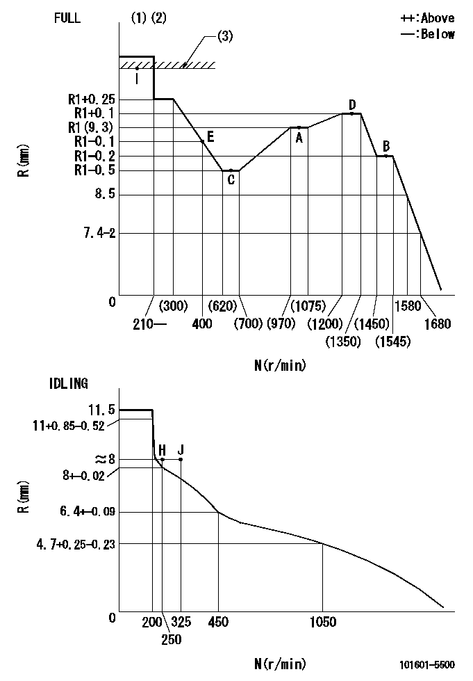
N:Pump speed
R:Rack position (mm)
(1)Torque cam stamping: T1
(2)Tolerance for racks not indicated: +-0.05mm.
(3)RACK LIMIT
----------
T1=D84
----------
----------
T1=D84
----------
Speed control lever angle
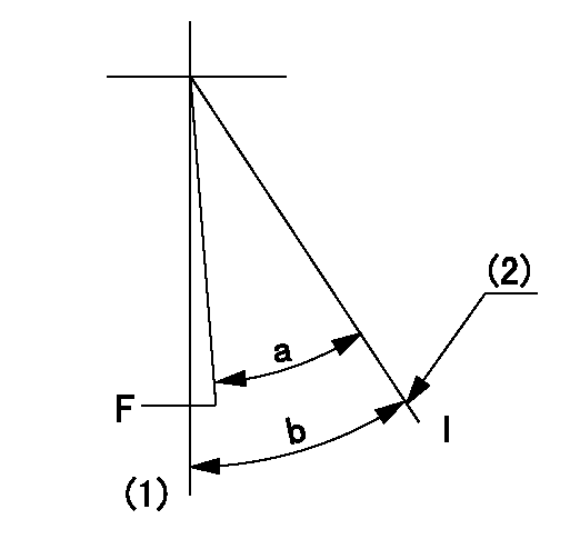
F:Full speed
I:Idle
(1)-
(2)Stopper bolt setting
----------
----------
a=(31deg)+-3deg b=34deg+-5deg
----------
----------
a=(31deg)+-3deg b=34deg+-5deg
Stop lever angle

N:Pump normal
S:Stop the pump.
----------
----------
a=40deg+-5deg b=40deg+-5deg
----------
----------
a=40deg+-5deg b=40deg+-5deg
Timing setting

(1)Pump vertical direction
(2)Position of gear's standard threaded hole at No 1 cylinder's beginning of injection
(3)-
(4)-
----------
----------
a=(70deg)
----------
----------
a=(70deg)
Information:
Spray starting fluid only while cranking the engine.
1. Heat the glow plugs (If equipped) for the approximate heating time shown in the STARTING AID CHART. 2. Turn the HEAT-START switch to START position. While cranking, spray starting fluid into the air inlet or air cleaner for approximately 1 second.
Wait at least 2 seconds before spraying starting fluid again.
3. If necessary, repeat the procedure.4. After the engine starts, it may be necessary to return the HEAT-START switch to the HEAT position until the engine runs smoothly.Jacket Water Heater (Attachment)
In very low temperatures, the lubricating oil must be warmed to allow starting. A jacket water heater can maintain the water temperature at approximately 90°F (32°C). The warm water will keep the oil in the upper part of the engine block warm enough to flow when starting.Dipstick Oil Heater
Contact your Caterpillar dealer before installing a dipstick crankcase oil heater.
Generator
Starting Single Unit Operation
1. Make all preliminary engine starting checks.2. Be sure the main or line circuit breaker is open.3. Start the engine and allow it to warm up.4. Close the main circuit breaker.5. Apply the load. Do not try to apply full load in one move, rather apply the load in increments to maintain system frequency at a constant level.Standby Generator Sets
Most standby units are automatic. They start, pickup the load, run and stop without an operator in attendance. Standby units can not change the governor control setting automatically. The throttle must be preset for the proper operation of that unit. Whenever the set is exercised or operated manually, be sure the throttle setting is correct for automatic operation. Check all switches to see they are properly set: Start Selector Switch in AUTOMATIC position and any Emergency Stop Switches in RUN position.Paralleling
Units may be paralleled at no load or paralleled with units under load. To parallel two or more units the following conditions must be met:1. Same phase rotation.2. Same voltage level.3. Same voltage droop.4. Same frequency.5. Voltages must be in phase.The first condition is established by "phased" wiring connections of initial installation.The second and third conditions are usually established by semi-permanent adjustments to the generator controls.The fourth and fifth conditions are under control of the operation in manual paralleling systems (or under automatic control in automatic paralleling systems).To Parallel
1. Start the unit to be paralleled.2. Turn the synchronizer lights on.3. After the engine has run long enough to warm up, bring it up to synchronous speed (the same frequency as the unit on the line). The synchronizing lights will begin to blink.4. Using the governor control, adjust the speed until the lights blink very slowly.5. The lights are off when the voltages of the two units are in phase. At this point, very quickly close the breaker while the lights are out. The frequency of the incoming unit should be slightly greater than the line frequency. This will allow the incoming unit to assume some of the load rather than add to the system load.Load Division
Once two units have been paralleled,
Have questions with 101601-5500?
Group cross 101601-5500 ZEXEL
101601-5500
INJECTION-PUMP ASSEMBLY