Information injection-pump assembly
BOSCH
9 400 614 616
9400614616
ZEXEL
101601-5492
1016015492
HINO
220006250A
220006250a
Rating:
Service parts 101601-5492 INJECTION-PUMP ASSEMBLY:
1.
_
6.
COUPLING PLATE
7.
COUPLING PLATE
8.
_
9.
_
11.
Nozzle and Holder
12.
Open Pre:MPa(Kqf/cm2)
19.6(200)
15.
NOZZLE SET
Cross reference number
BOSCH
9 400 614 616
9400614616
ZEXEL
101601-5492
1016015492
HINO
220006250A
220006250a
Zexel num
Bosch num
Firm num
Name
101601-5492
9 400 614 616
220006250A HINO
INJECTION-PUMP ASSEMBLY
W06D K
W06D K
Calibration Data:
Adjustment conditions
Test oil
1404 Test oil ISO4113 or {SAEJ967d}
1404 Test oil ISO4113 or {SAEJ967d}
Test oil temperature
degC
40
40
45
Nozzle and nozzle holder
105780-8140
Bosch type code
EF8511/9A
Nozzle
105780-0000
Bosch type code
DN12SD12T
Nozzle holder
105780-2080
Bosch type code
EF8511/9
Opening pressure
MPa
17.2
Opening pressure
kgf/cm2
175
Injection pipe
Outer diameter - inner diameter - length (mm) mm 6-2-600
Outer diameter - inner diameter - length (mm) mm 6-2-600
Overflow valve
131424-5720
Overflow valve opening pressure
kPa
255
221
289
Overflow valve opening pressure
kgf/cm2
2.6
2.25
2.95
Tester oil delivery pressure
kPa
157
157
157
Tester oil delivery pressure
kgf/cm2
1.6
1.6
1.6
Direction of rotation (viewed from drive side)
Right R
Right R
Injection timing adjustment
Direction of rotation (viewed from drive side)
Right R
Right R
Injection order
1-4-2-6-
3-5
Pre-stroke
mm
3.1
3.07
3.13
Beginning of injection position
Drive side NO.1
Drive side NO.1
Difference between angles 1
Cal 1-4 deg. 60 59.75 60.25
Cal 1-4 deg. 60 59.75 60.25
Difference between angles 2
Cyl.1-2 deg. 120 119.75 120.25
Cyl.1-2 deg. 120 119.75 120.25
Difference between angles 3
Cal 1-6 deg. 180 179.75 180.25
Cal 1-6 deg. 180 179.75 180.25
Difference between angles 4
Cal 1-3 deg. 240 239.75 240.25
Cal 1-3 deg. 240 239.75 240.25
Difference between angles 5
Cal 1-5 deg. 300 299.75 300.25
Cal 1-5 deg. 300 299.75 300.25
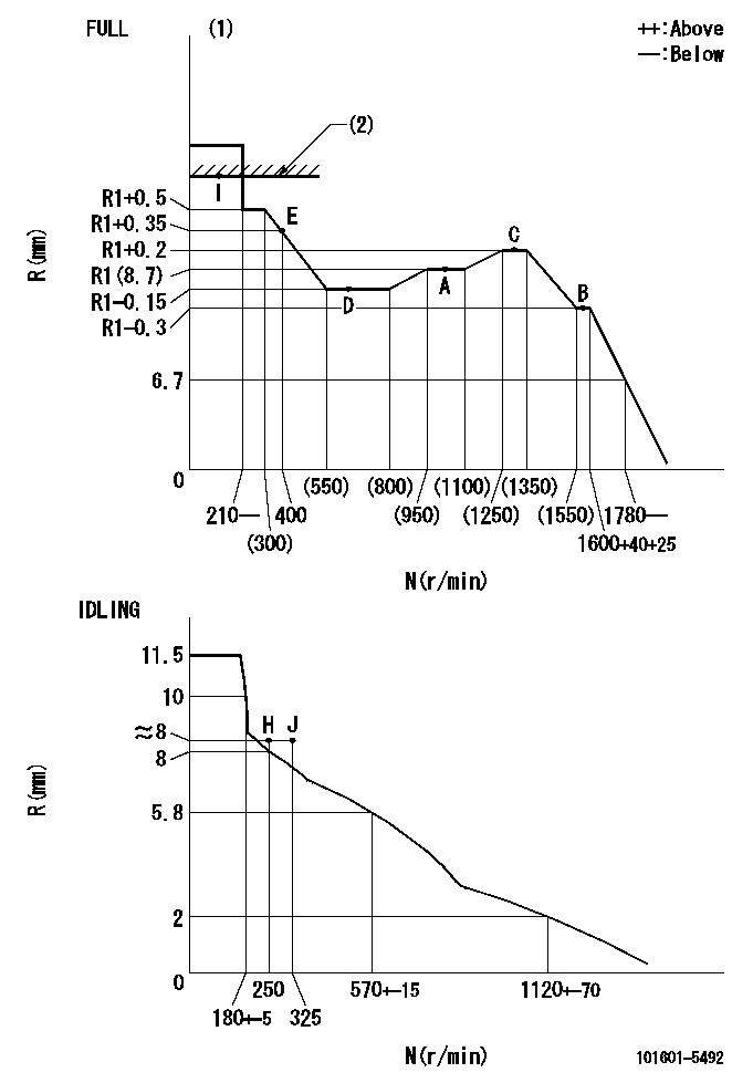
Injection quantity adjustment
Adjusting point
-
Rack position
8.7
Pump speed
r/min
1000
1000
1000
Average injection quantity
mm3/st.
46.6
44.6
48.6
Max. variation between cylinders
%
0
-3.5
3.5
Basic
*
Fixing the rack
*
Standard for adjustment of the maximum variation between cylinders
*
Injection quantity adjustment_02
Adjusting point
H
Rack position
8+-0.5
Pump speed
r/min
250
250
250
Average injection quantity
mm3/st.
8
6.5
9.5
Max. variation between cylinders
%
0
-10
10
Fixing the rack
*
Standard for adjustment of the maximum variation between cylinders
*
Injection quantity adjustment_03
Adjusting point
A
Rack position
R1(8.7)
Pump speed
r/min
1000
1000
1000
Average injection quantity
mm3/st.
46.6
45.6
47.6
Basic
*
Fixing the lever
*
Injection quantity adjustment_04
Adjusting point
B
Rack position
R1-0.3
Pump speed
r/min
1600
1600
1600
Average injection quantity
mm3/st.
45.2
43.2
47.2
Fixing the lever
*
Injection quantity adjustment_05
Adjusting point
C
Rack position
R1+0.2
Pump speed
r/min
1300
1300
1300
Average injection quantity
mm3/st.
52
50
54
Fixing the lever
*
Injection quantity adjustment_06
Adjusting point
D
Rack position
R1-0.15
Pump speed
r/min
650
650
650
Average injection quantity
mm3/st.
38
36
40
Fixing the lever
*
Injection quantity adjustment_07
Adjusting point
I
Rack position
-
Pump speed
r/min
100
100
100
Average injection quantity
mm3/st.
95
95
105
Fixing the lever
*
Rack limit
*
Injection quantity adjustment_08
Adjusting point
E
Rack position
R1+0.35
Pump speed
r/min
400
400
400
Average injection quantity
mm3/st.
28
24
32
Fixing the lever
*
Timer adjustment
Pump speed
r/min
1300+50
Advance angle
deg.
0
0
0
Remarks
Start
Start
Timer adjustment_02
Pump speed
r/min
1600
Advance angle
deg.
3.5
3.2
3.8
Remarks
Finish
Finish
Test data Ex:
Governor adjustment
N:Pump speed
R:Rack position (mm)
(1)Torque cam stamping: T1
(2)RACK LIMIT
----------
T1=C46
----------
----------
T1=C46
----------
Speed control lever angle
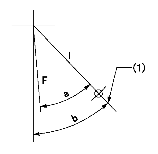
F:Full speed
I:Idle
(1)Stopper bolt set position 'H'
----------
----------
a=(45deg)+-3deg b=46deg+-5deg
----------
----------
a=(45deg)+-3deg b=46deg+-5deg
Stop lever angle

N:Pump normal
S:Stop the pump.
----------
----------
a=20deg+-5deg b=40deg+-5deg
----------
----------
a=20deg+-5deg b=40deg+-5deg
Timing setting

(1)Pump vertical direction
(2)Position of gear's standard threaded hole at No 1 cylinder's beginning of injection
(3)-
(4)-
----------
----------
a=(70deg)
----------
----------
a=(70deg)
Information:
Pre-Start Inspection And Procedures
1. Make a "walk-around" inspection of the engine and components for the oil, water or fuel leaks and general appearance. Correct minor adjustments before they develop into major repair jobs.2. Check the crankcase oil level. Maintain the oil level between the ADD and FULL marks on the dipstick. See OIL SPECIFICATIONS for type of oil to use. 3. Check oil level(s) on driven equipment.
Check the engine coolant level when the engine is cool. If the engine is warm, steam may spray outward under high pressure and cause personal injury.
4. Check the engine jacket coolant level. Slowly turn the pressure cap until the cap is removed. Maintain coolant level to the base of the fill pipe. 5. Check the fuel supply. Keep fuel tanks full, as partially filled tanks will collect moisture. See the FUEL SPECIFICATIONS for type of fuel.Keep The Fuel Supply Clean
6. Open the raw water valve on the engine jacket heat exchanger system (if so equipped). Prime the raw water pump if the raw water system has been drained.7. Reset shutoff devices. See the topic, ATTACHMENTS, Emergency Shutoff Devices and Alarms.
OIL PRESSURE RESET
OVERSPEED RESETIf the engine is equipped with an air safety shutoff control, and was tripped to the shutoff position, reset the latch to the run position.
AIR SHUTOFF RESET8. Open the fuel supply valve. If the engine has not run for some time it may be necessary to prime the system. See the topic, PRIMING THE FUEL SYSTEM.9. Disconnect any battery charger which is not protected against starting motor drain.10. Disengage the clutch, or open the circuit breaker on a generator set.
Have questions with 101601-5492?
Group cross 101601-5492 ZEXEL
Hino
Hino
Hino
Hino
Hino
Hino
101601-5492
9 400 614 616
220006250A
INJECTION-PUMP ASSEMBLY
W06D
W06D