Information injection-pump assembly
BOSCH
9 400 614 615
9400614615
ZEXEL
101601-5486
1016015486
HINO
220006232A
220006232a

Rating:
Service parts 101601-5486 INJECTION-PUMP ASSEMBLY:
1.
_
6.
COUPLING PLATE
7.
COUPLING PLATE
8.
_
9.
_
11.
Nozzle and Holder
12.
Open Pre:MPa(Kqf/cm2)
19.6(200)
15.
NOZZLE SET
Cross reference number
BOSCH
9 400 614 615
9400614615
ZEXEL
101601-5486
1016015486
HINO
220006232A
220006232a
Zexel num
Bosch num
Firm num
Name
101601-5486
9 400 614 615
220006232A HINO
INJECTION-PUMP ASSEMBLY
W06E-E * K
W06E-E * K
Calibration Data:
Adjustment conditions
Test oil
1404 Test oil ISO4113 or {SAEJ967d}
1404 Test oil ISO4113 or {SAEJ967d}
Test oil temperature
degC
40
40
45
Nozzle and nozzle holder
105780-8140
Bosch type code
EF8511/9A
Nozzle
105780-0000
Bosch type code
DN12SD12T
Nozzle holder
105780-2080
Bosch type code
EF8511/9
Opening pressure
MPa
17.2
Opening pressure
kgf/cm2
175
Injection pipe
Outer diameter - inner diameter - length (mm) mm 6-2-600
Outer diameter - inner diameter - length (mm) mm 6-2-600
Overflow valve
134424-0920
Overflow valve opening pressure
kPa
162
147
177
Overflow valve opening pressure
kgf/cm2
1.65
1.5
1.8
Tester oil delivery pressure
kPa
157
157
157
Tester oil delivery pressure
kgf/cm2
1.6
1.6
1.6
Direction of rotation (viewed from drive side)
Right R
Right R
Injection timing adjustment
Direction of rotation (viewed from drive side)
Right R
Right R
Injection order
1-4-2-6-
3-5
Pre-stroke
mm
3.45
3.42
3.48
Beginning of injection position
Drive side NO.1
Drive side NO.1
Difference between angles 1
Cal 1-4 deg. 60 59.75 60.25
Cal 1-4 deg. 60 59.75 60.25
Difference between angles 2
Cyl.1-2 deg. 120 119.75 120.25
Cyl.1-2 deg. 120 119.75 120.25
Difference between angles 3
Cal 1-6 deg. 180 179.75 180.25
Cal 1-6 deg. 180 179.75 180.25
Difference between angles 4
Cal 1-3 deg. 240 239.75 240.25
Cal 1-3 deg. 240 239.75 240.25
Difference between angles 5
Cal 1-5 deg. 300 299.75 300.25
Cal 1-5 deg. 300 299.75 300.25
Injection quantity adjustment
Adjusting point
-
Rack position
11.3
Pump speed
r/min
1000
1000
1000
Average injection quantity
mm3/st.
66.5
64.5
68.5
Max. variation between cylinders
%
0
-3.5
3.5
Basic
*
Fixing the rack
*
Standard for adjustment of the maximum variation between cylinders
*
Injection quantity adjustment_02
Adjusting point
H
Rack position
9.5+-0.5
Pump speed
r/min
250
250
250
Each cylinder's injection qty
mm3/st.
16.4
15.4
17.4
Fixing the rack
*
Standard for adjustment of the maximum variation between cylinders
*
Injection quantity adjustment_03
Adjusting point
A
Rack position
R1(11.3)
Pump speed
r/min
1000
1000
1000
Average injection quantity
mm3/st.
66.5
65.5
67.5
Basic
*
Fixing the lever
*
Injection quantity adjustment_04
Adjusting point
B
Rack position
R1-0.15
Pump speed
r/min
1500
1500
1500
Average injection quantity
mm3/st.
63
59
67
Fixing the lever
*
Injection quantity adjustment_05
Adjusting point
C
Rack position
R1-0.45
Pump speed
r/min
600
600
600
Average injection quantity
mm3/st.
46.8
42.8
50.8
Fixing the lever
*
Injection quantity adjustment_06
Adjusting point
I
Rack position
-
Pump speed
r/min
100
100
100
Average injection quantity
mm3/st.
124
124
134
Fixing the lever
*
Rack limit
*
Timer adjustment
Pump speed
r/min
960--
Advance angle
deg.
0
0
0
Load
1/4
Remarks
Start
Start
Timer adjustment_02
Pump speed
r/min
910
Advance angle
deg.
0.3
Load
1/4
Timer adjustment_03
Pump speed
r/min
1010
Advance angle
deg.
1
0.7
1.3
Load
4/4
Timer adjustment_04
Pump speed
r/min
1210
Advance angle
deg.
1
0.7
1.3
Load
3/4
Timer adjustment_05
Pump speed
r/min
1510
Advance angle
deg.
6
5.7
6.3
Load
4/4
Remarks
Finish
Finish
Test data Ex:
Governor adjustment
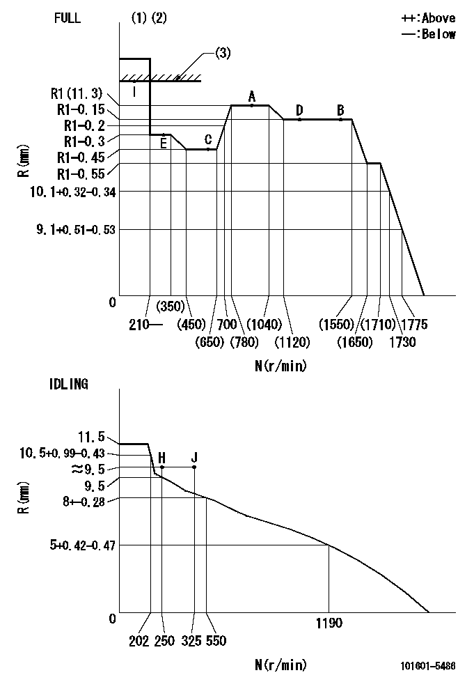
N:Pump speed
R:Rack position (mm)
(1)Torque cam stamping: T1
(2)Tolerance for racks not indicated: +-0.05mm.
(3)RACK LIMIT
----------
T1=H53
----------
----------
T1=H53
----------
Speed control lever angle
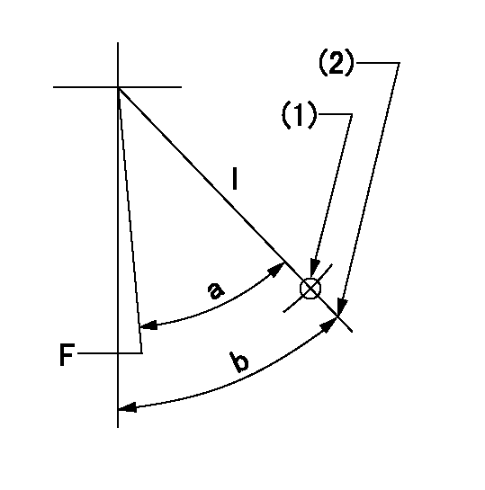
F:Full speed
I:Idle
(1)Use the hole at R = aa
(2)Stopper bolt set position 'H'
----------
aa=50mm
----------
a=(41deg)+-3deg b=46deg+-5deg
----------
aa=50mm
----------
a=(41deg)+-3deg b=46deg+-5deg
Stop lever angle
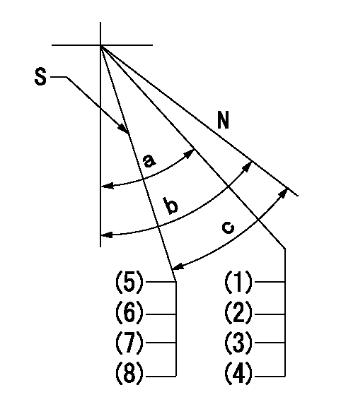
N:Pump normal
S:Engine stop
(1)Engine normal
(2)Rack position = aa
(3)Set the stopper bolt (at shipping).
(4)(Apply red paint after setting.)
(5)At speed lever full position and pump speed bb, set the stopper screw at rack position cc (non-injection rack position).
(6)Then confirm non-injection at speed lever idle speed = dd.
(7)Set the idle speed at ee using the speed lever and move the stop lever 2 or 3 turns. Confirm that the rack is not pulled back.
(8)After adjustment, apply red paint.
----------
aa=15+-0.1mm bb=1500r/min cc=6.6-0.5mm dd=250r/min ee=0r/min
----------
a=(35deg) b=40deg+-5deg c=26deg+-5deg
----------
aa=15+-0.1mm bb=1500r/min cc=6.6-0.5mm dd=250r/min ee=0r/min
----------
a=(35deg) b=40deg+-5deg c=26deg+-5deg
Timing setting

(1)Pump vertical direction
(2)Position of gear's standard threaded hole at No 1 cylinder's beginning of injection
(3)-
(4)-
----------
----------
a=(70deg)
----------
----------
a=(70deg)
Information:
This guide contains operation instructions and lubrication and maintenance information.The operation section is a reference for the new operator and a refresher for the experienced one. Read - study - and keep it handy.Illustrations guide the operator through correct procedures of checking, starting, operating and stopping the engine.The maintenance section is a guide to equipment care. The illustrated, step-by-step instructions are grouped by servicing intervals. Items in the "Lubrication and Maintenance Chart" are referenced to the detailed instructions that follow.Use the service meter to determine servicing intervals. Calendar intervals shown may be used instead of service meter intervals if they provide more convenient servicing schedules and approximate the indicated service meter reading. Recommended service should always be performed at the interval that occurs first.Under extremely severe, dusty or wet operating conditions, more frequent lubrication than is specified in the "Lubrication and Maintenance Chart" may be necessary.Perform service on items at multiples of the original requirement. For example, at Every 500 Service Meter Units, also service those items listed under Every 250 Service Meter Units, Every 50 Service Meter Units and Every 10 Service Meter Units.Some photographs in this publication show details or attachments that may be different from your engine. Also, guards and covers may have been removed for illustrative purposes.Continuing improvement and advancement of product design may have caused changes to your engine which are not included in this publication.Each publication is reviewed and revised, as required, to update and include these changes in later editions.Whenever a question arises regarding your engine or this publication, please consult your Caterpillar dealer for the latest available information.Engine Identification
Caterpillar engines are identified with SERIAL NUMBERS and ARRANGEMENT NUMBERS. In some cases MODIFICATION NUMBERS are also used. These numbers are shown on the serial number plate mounted on the engine.Caterpillar dealers need all of these numbers to determine which components were included on the engine when it was assembled at the factory. This permits accurate identification of replacement part numbers.Ordering Parts
Quality Caterpillar replacement parts are available from Caterpillar dealers throughout the world. Their parts stocks are up to date and include all parts normally required to protect your investment in Caterpillar engines. When ordering parts, your order should specify the quantity, part number, part name and serial number, arrangement number and modification number of the engine for which the parts are needed. If in doubt about the part number, please provide your dealer with a complete description of the needed item.
Have questions with 101601-5486?
Group cross 101601-5486 ZEXEL
Hino
Hino
Hino
Hino
Hino
101601-5486
9 400 614 615
220006232A
INJECTION-PUMP ASSEMBLY
W06E-E
W06E-E