Information injection-pump assembly
BOSCH
F 01G 09U 02V
f01g09u02v
ZEXEL
101601-5485
1016015485

Rating:
Service parts 101601-5485 INJECTION-PUMP ASSEMBLY:
1.
_
6.
COUPLING PLATE
7.
COUPLING PLATE
8.
_
9.
_
11.
Nozzle and Holder
23600-2142A
12.
Open Pre:MPa(Kqf/cm2)
19.6{200}
15.
NOZZLE SET
Cross reference number
BOSCH
F 01G 09U 02V
f01g09u02v
ZEXEL
101601-5485
1016015485
Zexel num
Bosch num
Firm num
Name
Calibration Data:
Adjustment conditions
Test oil
1404 Test oil ISO4113 or {SAEJ967d}
1404 Test oil ISO4113 or {SAEJ967d}
Test oil temperature
degC
40
40
45
Nozzle and nozzle holder
105780-8140
Bosch type code
EF8511/9A
Nozzle
105780-0000
Bosch type code
DN12SD12T
Nozzle holder
105780-2080
Bosch type code
EF8511/9
Opening pressure
MPa
17.2
Opening pressure
kgf/cm2
175
Injection pipe
Outer diameter - inner diameter - length (mm) mm 6-2-600
Outer diameter - inner diameter - length (mm) mm 6-2-600
Overflow valve
134424-0920
Overflow valve opening pressure
kPa
162
147
177
Overflow valve opening pressure
kgf/cm2
1.65
1.5
1.8
Tester oil delivery pressure
kPa
157
157
157
Tester oil delivery pressure
kgf/cm2
1.6
1.6
1.6
Direction of rotation (viewed from drive side)
Right R
Right R
Injection timing adjustment
Direction of rotation (viewed from drive side)
Right R
Right R
Injection order
1-4-2-6-
3-5
Pre-stroke
mm
3.45
3.42
3.48
Beginning of injection position
Drive side NO.1
Drive side NO.1
Difference between angles 1
Cal 1-4 deg. 60 59.75 60.25
Cal 1-4 deg. 60 59.75 60.25
Difference between angles 2
Cyl.1-2 deg. 120 119.75 120.25
Cyl.1-2 deg. 120 119.75 120.25
Difference between angles 3
Cal 1-6 deg. 180 179.75 180.25
Cal 1-6 deg. 180 179.75 180.25
Difference between angles 4
Cal 1-3 deg. 240 239.75 240.25
Cal 1-3 deg. 240 239.75 240.25
Difference between angles 5
Cal 1-5 deg. 300 299.75 300.25
Cal 1-5 deg. 300 299.75 300.25
Injection quantity adjustment
Adjusting point
-
Rack position
11.3
Pump speed
r/min
1000
1000
1000
Average injection quantity
mm3/st.
66.5
64.5
68.5
Max. variation between cylinders
%
0
-3.5
3.5
Basic
*
Fixing the rack
*
Standard for adjustment of the maximum variation between cylinders
*
Injection quantity adjustment_02
Adjusting point
H
Rack position
9.5+-0.5
Pump speed
r/min
250
250
250
Each cylinder's injection qty
mm3/st.
16.4
15.4
17.4
Fixing the rack
*
Standard for adjustment of the maximum variation between cylinders
*
Injection quantity adjustment_03
Adjusting point
A
Rack position
R1(11.3)
Pump speed
r/min
1000
1000
1000
Average injection quantity
mm3/st.
66.5
65.5
67.5
Basic
*
Fixing the lever
*
Injection quantity adjustment_04
Adjusting point
B
Rack position
R1-0.15
Pump speed
r/min
1500
1500
1500
Average injection quantity
mm3/st.
63
59
67
Fixing the lever
*
Injection quantity adjustment_05
Adjusting point
C
Rack position
R1-0.45
Pump speed
r/min
600
600
600
Average injection quantity
mm3/st.
46.8
42.8
50.8
Fixing the lever
*
Injection quantity adjustment_06
Adjusting point
I
Rack position
-
Pump speed
r/min
100
100
100
Average injection quantity
mm3/st.
124
124
134
Fixing the lever
*
Rack limit
*
Timer adjustment
Pump speed
r/min
960--
Advance angle
deg.
0
0
0
Load
1/4
Remarks
Start
Start
Timer adjustment_02
Pump speed
r/min
910
Advance angle
deg.
0.3
Load
1/4
Timer adjustment_03
Pump speed
r/min
1010
Advance angle
deg.
1
0.7
1.3
Load
4/4
Timer adjustment_04
Pump speed
r/min
1210
Advance angle
deg.
1
0.7
1.3
Load
3/4
Timer adjustment_05
Pump speed
r/min
1510
Advance angle
deg.
6
5.7
6.3
Load
4/4
Remarks
Finish
Finish
Test data Ex:
Governor adjustment
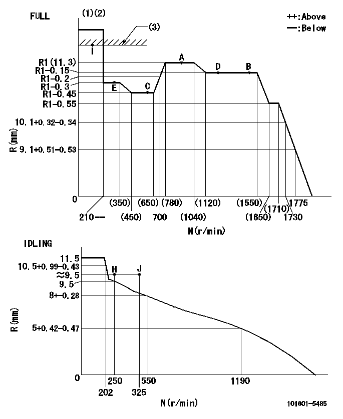
N:Pump speed
R:Rack position (mm)
(1)Torque cam stamping: T1
(2)Tolerance for racks not indicated: +-0.05mm.
(3)RACK LIMIT
----------
T1=H53
----------
----------
T1=H53
----------
Speed control lever angle
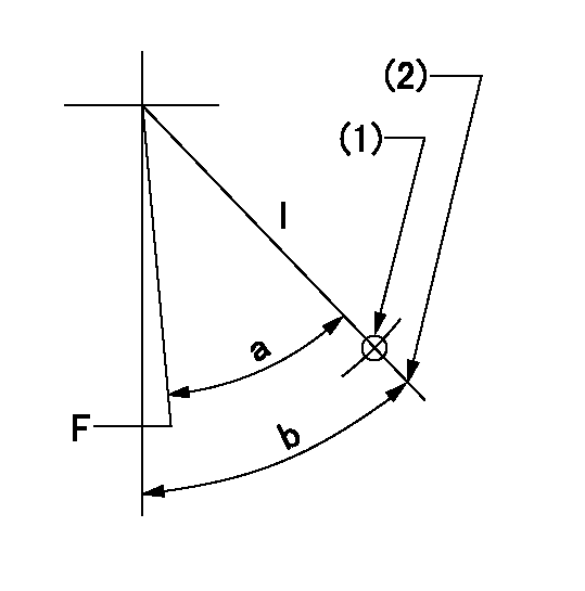
F:Full speed
I:Idle
(1)Use the hole at R = aa
(2)Stopper bolt set position 'H'
----------
aa=50mm
----------
a=(41deg)+-3deg b=46deg+-5deg
----------
aa=50mm
----------
a=(41deg)+-3deg b=46deg+-5deg
Stop lever angle
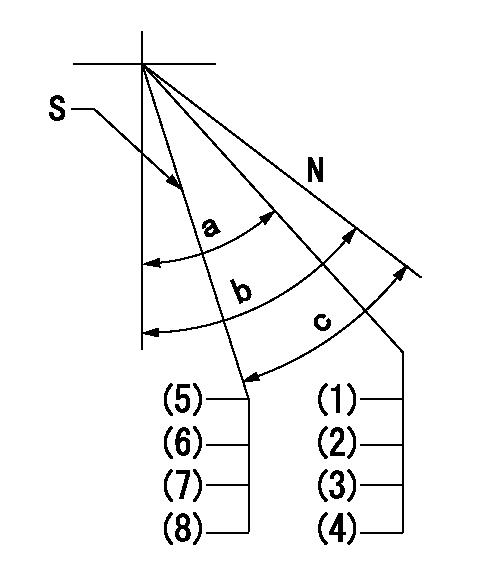
N:Pump normal
S:Engine stop
(1)Engine normal
(2)Rack position = aa
(3)Set the stopper bolt (at shipping).
(4)(Apply red paint after setting.)
(5)At speed lever full position and pump speed bb, set the stopper screw at rack position cc (non-injection rack position).
(6)Confirm non-injection with the speed lever in the idle position at speed = dd.
(7)With the speed lever in the idle position at speed = ee, operate the stop lever 2 or 3 times and confirm that the rack does not stick.
(8)After adjustment, apply red paint.
----------
aa=15+-0.1mm bb=1500r/min cc=6.6-0.5mm dd=250r/min ee=0r/min
----------
a=(35deg) b=40deg+-5deg c=26deg+-5deg
----------
aa=15+-0.1mm bb=1500r/min cc=6.6-0.5mm dd=250r/min ee=0r/min
----------
a=(35deg) b=40deg+-5deg c=26deg+-5deg
Timing setting

(1)Pump vertical direction
(2)Position of gear's standard threaded hole at No 1 cylinder's beginning of injection
(3)-
(4)-
----------
----------
a=(70deg)
----------
----------
a=(70deg)
Information:
Appendix
Configuration Information
Table 7
Over-Temp
Inlet Over-Temperature Alarm
Condition Expected Value
Enable Alarm Yes
Log Alarm Transitions Yes
Active Output During Alarm Output 1
Output function ON only during alarm
Assert Alarm Above
650 °C (1202 °F)
Hysteresis
20 °C (68 °F)
Upon Over Temperature extend alarm for 60 seconds
Table 8
Over-Pres
Over-Pressure Warning
Condition Expected Value
Enable Alarm Yes
Log Alarm Transitions Yes
Active Output During Alarm Output 1
Output Function ON only during alarm
Assert Alarm when the measured pressure exceeds 7" of Hg for 5% of the time during a 60 min measurement interval
Over-Pressure Alarm
Condition Expected Value
Enable Alarm Yes
Log Alarm Transitions Yes
Active Output During Alarm Output 2
Output Function Latched ON upon alarm
Assert alarm when the measured pressure exceeds 8" of Hg for 5% of the time during a 60 min measurement interval
Table 9
TC-Fail (1)
Open Thermocouple Detect
Condition Expected Value
Enable Alarm Yes
Log Alarm Transitions Yes
Output During Alarm Output 1
Output Function Latched ON upon alarm
Assert alarm if measured temperature is above
1000 °C (1832 °F)
Shorted Thermocouple Detect
Condition Expected Value
Enable Alarm Yes
Log Alarm Transitions Yes
Output During Alarm Output 1
Output Function Latched ON upon alarm
Assert alarm if pressure is greater than 1" of Hg for 10 min and measured temperature does not exceed
120 °C (248 °F)
( 1 ) Output selection applies to both open and shorted alarms
Table 10
Pressure Sensor Fail
No Change Alarm
Condition Expected Value
Enable Alarm Yes
Log Alarm Transitions Yes
Active Outputs During Alarm Output 1
Output Function Latched ON upon Alarm
Assert alarm if exhaust temperature is above
250 °C (482 °F) for 10 min and the pressure doesn't change by at least 0.25" of Hg
Negative Pressure Alarm
Condition Expected Value
Enable Alarm Yes
Log Alarm Transitions Yes
Active Output During Alarm Output 1
Output Function Latched ON during alarm
Assert Alarm if temperature is above
200 °C (392 °F) for 10 min and the pressure is less than −1" of