Information injection-pump assembly
BOSCH
F 01G 09U 02U
f01g09u02u
ZEXEL
101601-5484
1016015484
HINO
220006231A
220006231a

Rating:
Service parts 101601-5484 INJECTION-PUMP ASSEMBLY:
1.
_
6.
COUPLING PLATE
7.
COUPLING PLATE
8.
_
9.
_
11.
Nozzle and Holder
23600-2142A
12.
Open Pre:MPa(Kqf/cm2)
19.6{200}
15.
NOZZLE SET
Cross reference number
BOSCH
F 01G 09U 02U
f01g09u02u
ZEXEL
101601-5484
1016015484
HINO
220006231A
220006231a
Zexel num
Bosch num
Firm num
Name
Calibration Data:
Adjustment conditions
Test oil
1404 Test oil ISO4113 or {SAEJ967d}
1404 Test oil ISO4113 or {SAEJ967d}
Test oil temperature
degC
40
40
45
Nozzle and nozzle holder
105780-8210
Nozzle
105780-0070
Nozzle holder
105780-2080
Bosch type code
EF8511/9
Opening pressure
MPa
17.2
Opening pressure
kgf/cm2
175
Injection pipe
Outer diameter - inner diameter - length (mm) mm 6-2-600
Outer diameter - inner diameter - length (mm) mm 6-2-600
Overflow valve
134424-0920
Overflow valve opening pressure
kPa
162
147
177
Overflow valve opening pressure
kgf/cm2
1.65
1.5
1.8
Tester oil delivery pressure
kPa
157
157
157
Tester oil delivery pressure
kgf/cm2
1.6
1.6
1.6
Direction of rotation (viewed from drive side)
Right R
Right R
Injection timing adjustment
Direction of rotation (viewed from drive side)
Right R
Right R
Injection order
1-4-2-6-
3-5
Pre-stroke
mm
3.45
3.42
3.48
Beginning of injection position
Drive side NO.1
Drive side NO.1
Difference between angles 1
Cal 1-4 deg. 60 59.75 60.25
Cal 1-4 deg. 60 59.75 60.25
Difference between angles 2
Cyl.1-2 deg. 120 119.75 120.25
Cyl.1-2 deg. 120 119.75 120.25
Difference between angles 3
Cal 1-6 deg. 180 179.75 180.25
Cal 1-6 deg. 180 179.75 180.25
Difference between angles 4
Cal 1-3 deg. 240 239.75 240.25
Cal 1-3 deg. 240 239.75 240.25
Difference between angles 5
Cal 1-5 deg. 300 299.75 300.25
Cal 1-5 deg. 300 299.75 300.25
Injection quantity adjustment
Adjusting point
-
Rack position
11
Pump speed
r/min
900
900
900
Average injection quantity
mm3/st.
66.9
64.9
68.9
Max. variation between cylinders
%
0
-3.5
3.5
Basic
*
Fixing the rack
*
Standard for adjustment of the maximum variation between cylinders
*
Injection quantity adjustment_02
Adjusting point
H
Rack position
9.5+-0.5
Pump speed
r/min
250
250
250
Each cylinder's injection qty
mm3/st.
18.5
17.5
19.5
Fixing the rack
*
Standard for adjustment of the maximum variation between cylinders
*
Injection quantity adjustment_03
Adjusting point
A
Rack position
R1(11)
Pump speed
r/min
900
900
900
Average injection quantity
mm3/st.
66.9
65.9
67.9
Basic
*
Fixing the lever
*
Injection quantity adjustment_04
Adjusting point
B
Rack position
R1+0.05
Pump speed
r/min
1500
1500
1500
Average injection quantity
mm3/st.
68.9
64.9
72.9
Fixing the lever
*
Injection quantity adjustment_05
Adjusting point
C
Rack position
R1-0.4
Pump speed
r/min
600
600
600
Average injection quantity
mm3/st.
57.9
53.9
61.9
Fixing the lever
*
Injection quantity adjustment_06
Adjusting point
I
Rack position
-
Pump speed
r/min
100
100
100
Average injection quantity
mm3/st.
127.5
127.5
137.5
Fixing the lever
*
Rack limit
*
Timer adjustment
Pump speed
r/min
960--
Advance angle
deg.
0
0
0
Load
1/4
Remarks
Start
Start
Timer adjustment_02
Pump speed
r/min
910
Advance angle
deg.
0.3
Load
1/4
Timer adjustment_03
Pump speed
r/min
1010
Advance angle
deg.
1
0.7
1.3
Load
4/4
Timer adjustment_04
Pump speed
r/min
1210
Advance angle
deg.
1
0.7
1.3
Load
3/4
Timer adjustment_05
Pump speed
r/min
1510
Advance angle
deg.
6
5.7
6.3
Load
4/4
Remarks
Finish
Finish
Test data Ex:
Governor adjustment
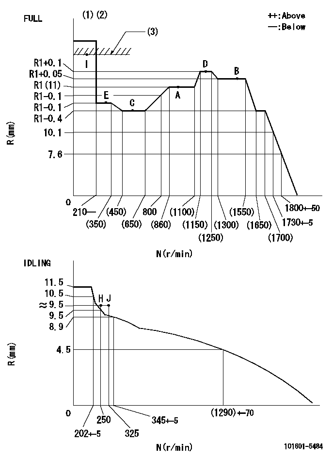
N:Pump speed
R:Rack position (mm)
(1)Torque cam stamping: T1
(2)Tolerance for racks not indicated: +-0.05mm.
(3)RACK LIMIT
----------
T1=E34
----------
----------
T1=E34
----------
Speed control lever angle
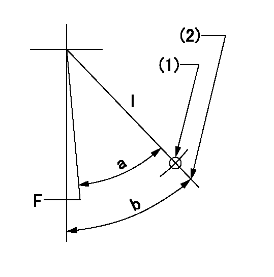
F:Full speed
I:Idle
(1)Use the hole at R = aa
(2)Stopper bolt set position 'H'
----------
aa=50mm
----------
a=(41deg)+-3deg b=46deg+-5deg
----------
aa=50mm
----------
a=(41deg)+-3deg b=46deg+-5deg
Stop lever angle
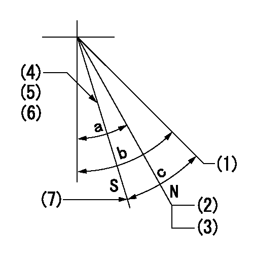
N:Engine normal (pump normal)
S:Engine stop
(1)Pump normal
(2)Set the stopper bolt at rack = aa (at shipping).
(3)After setting, apply red paint.
(4)At speed lever full position and pump speed bb, set the stopper screw at rack position cc (non-injection rack position).
(5)Confirm non-injection with the speed lever in the idle position at speed = dd.
(6)With the speed lever in the idle position at speed = ee, operate the stop lever 2 or 3 times and confirm that the rack does not stick.
(7)After adjustment, apply red paint.
----------
aa=15+-0.1mm bb=1500r/min cc=6.6-0.5mm dd=250r/min ee=0r/min
----------
a=(35deg) b=40deg+-5deg c=(26deg)+-5deg
----------
aa=15+-0.1mm bb=1500r/min cc=6.6-0.5mm dd=250r/min ee=0r/min
----------
a=(35deg) b=40deg+-5deg c=(26deg)+-5deg
Timing setting

(1)Pump vertical direction
(2)Position of gear's standard threaded hole at No 1 cylinder's beginning of injection
(3)-
(4)-
----------
----------
a=(70deg)
----------
----------
a=(70deg)
Information:
7. Remove inner fuel lines (13). 8. Remove Jacobs washers (14) and Jacobs shims (15) from the Jacobs stud assemblies. 9. Remove bolt (17) and two Jacobs stud assemblies (16) that hold the rocker shaft assembly to the head. Remove rocker shaft assembly (18). 10. Remove Jacobs exhaust valve bridges (20) from the exhaust valves only. The intake valves have the Caterpillar intake valve bridges. Remove the Caterpillar intake valve bridges (19).Install Jacobs Engine Brake
Do each step for each end of the engine. The front half is shown.1. Put clean engine oil on the bridges and dowels.2. Install Jacobs exhaust valve bridges (20) and the Caterpillar intake valve bridges (19) on the dowels.3. Keep hand pressure on the bridges, and turn the adjustment screw clockwise until contact is made with the valve stem. Turn the screw an extra 20 ° to 30 °. This will make the dowel straight in the guide and compensate for gap (slack) in the threads. Hold the adjustment screw in this position, and tighten the locknut to a torque of 28 4 N m (21 3 lb.ft.). 4. Put rocker shaft assembly (18) in position on the cylinder head. 5. Install Jacobs washers (21) on the Jacobs stud assemblies (16). Put clean oil on the threads, and install washer and bolt (17) and Jacobs stud assemblies (16). Tighten the center bolt and Jacobs stud assemblies in increments of 70 N m (50 lb.ft.) each until a final torque of 450 N m (330 lb.ft.) is obtained.6. Make an adjustment to the valves to have a clearance of .015 (0.38 mm) for the intake valves and .030 (0.76 mm) for the exhaust valves. Tighten the locknuts to a torque of 28 4 N m (21 3 lb.ft.), and check the valve clearance again. See Testing And Adjusting for the correct procedure. 7. Install a new Jacobs O-ring seal (22) on the Jacobs oil supply adapter in the rocker shaft assembly. Put clean oil on the Jacobs O-ring seal.
Do not cause damage to the O-ring seals on the inner fuel lines.
8. Install inner fuel lines (13). Tighten the fuel line nuts to a torque of 40 7 N m (30 5 lb.ft.) with tooling (A) and (B). The Jacobs brake for the 3406B Truck Engine has only one support bracket (11).9. Put Jacobs support brackets (11) in position as shown. Put oil on the threads of Jacobs bolts (12). Install the washers on the Jacobs bolts. Install Jacobs bolts (12) that hold the Jacobs support bracket in place. Tighten the Jacobs bolts to a torque of 450 N m (330 lb.ft.). 10. Install Jacobs washers (14) on the Jacobs stud assemblies.
Be extra careful not to cause damage to the Jacobs oil supply adapter O-ring seal when the Jacobs brake housing assembly is installed.
The brake housing assembly with the mark "FRONT" on it must