Information injection-pump assembly
BOSCH
9 400 614 613
9400614613
ZEXEL
101601-5467
1016015467
HINO
220006213A
220006213a

Rating:
Service parts 101601-5467 INJECTION-PUMP ASSEMBLY:
1.
_
6.
COUPLING PLATE
7.
COUPLING PLATE
8.
_
9.
_
11.
Nozzle and Holder
12.
Open Pre:MPa(Kqf/cm2)
19.6(200)
15.
NOZZLE SET
Cross reference number
BOSCH
9 400 614 613
9400614613
ZEXEL
101601-5467
1016015467
HINO
220006213A
220006213a
Zexel num
Bosch num
Firm num
Name
101601-5467
9 400 614 613
220006213A HINO
INJECTION-PUMP ASSEMBLY
W06E * K
W06E * K
Calibration Data:
Adjustment conditions
Test oil
1404 Test oil ISO4113 or {SAEJ967d}
1404 Test oil ISO4113 or {SAEJ967d}
Test oil temperature
degC
40
40
45
Nozzle and nozzle holder
105780-8210
Nozzle
105780-0070
Bosch type code
DN12SD12T-1
Nozzle holder
105780-2080
Bosch type code
EF8511/9
Opening pressure
MPa
17.2
Opening pressure
kgf/cm2
175
Injection pipe
Outer diameter - inner diameter - length (mm) mm 6-2-600
Outer diameter - inner diameter - length (mm) mm 6-2-600
Overflow valve
134424-0920
Overflow valve opening pressure
kPa
162
147
177
Overflow valve opening pressure
kgf/cm2
1.65
1.5
1.8
Tester oil delivery pressure
kPa
157
157
157
Tester oil delivery pressure
kgf/cm2
1.6
1.6
1.6
Direction of rotation (viewed from drive side)
Right R
Right R
Injection timing adjustment
Direction of rotation (viewed from drive side)
Right R
Right R
Injection order
1-4-2-6-
3-5
Pre-stroke
mm
3.45
3.42
3.48
Beginning of injection position
Drive side NO.1
Drive side NO.1
Difference between angles 1
Cal 1-4 deg. 60 59.75 60.25
Cal 1-4 deg. 60 59.75 60.25
Difference between angles 2
Cyl.1-2 deg. 120 119.75 120.25
Cyl.1-2 deg. 120 119.75 120.25
Difference between angles 3
Cal 1-6 deg. 180 179.75 180.25
Cal 1-6 deg. 180 179.75 180.25
Difference between angles 4
Cal 1-3 deg. 240 239.75 240.25
Cal 1-3 deg. 240 239.75 240.25
Difference between angles 5
Cal 1-5 deg. 300 299.75 300.25
Cal 1-5 deg. 300 299.75 300.25
Injection quantity adjustment
Adjusting point
-
Rack position
10.7
Pump speed
r/min
900
900
900
Average injection quantity
mm3/st.
63.7
61.7
65.7
Max. variation between cylinders
%
0
-3.5
3.5
Basic
*
Fixing the rack
*
Standard for adjustment of the maximum variation between cylinders
*
Injection quantity adjustment_02
Adjusting point
H
Rack position
9.3+-0.5
Pump speed
r/min
250
250
250
Each cylinder's injection qty
mm3/st.
17
16
18
Fixing the rack
*
Standard for adjustment of the maximum variation between cylinders
*
Injection quantity adjustment_03
Adjusting point
A
Rack position
R1(10.7)
Pump speed
r/min
900
900
900
Average injection quantity
mm3/st.
63.7
62.7
64.7
Basic
*
Fixing the lever
*
Injection quantity adjustment_04
Adjusting point
B
Rack position
R1+0.05
Pump speed
r/min
1500
1500
1500
Average injection quantity
mm3/st.
61.7
57.7
65.7
Fixing the lever
*
Injection quantity adjustment_05
Adjusting point
C
Rack position
R1-0.4
Pump speed
r/min
600
600
600
Average injection quantity
mm3/st.
55.3
51.3
59.3
Fixing the lever
*
Injection quantity adjustment_06
Adjusting point
I
Rack position
-
Pump speed
r/min
100
100
100
Average injection quantity
mm3/st.
122
122
132
Fixing the lever
*
Rack limit
*
Timer adjustment
Pump speed
r/min
960--
Advance angle
deg.
0
0
0
Remarks
Start
Start
Timer adjustment_02
Pump speed
r/min
1010
Advance angle
deg.
1
0.7
1.3
Timer adjustment_03
Pump speed
r/min
-
Advance angle
deg.
1
0.7
1.3
Remarks
Measure the actual speed.
Measure the actual speed.
Timer adjustment_04
Pump speed
r/min
1510
Advance angle
deg.
6
5.7
6.3
Remarks
Finish
Finish
Test data Ex:
Governor adjustment
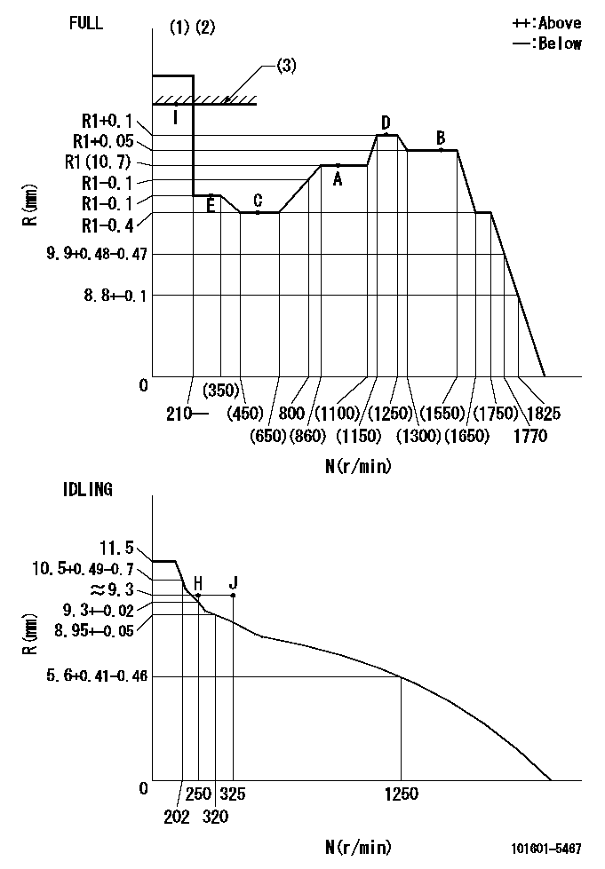
N:Pump speed
R:Rack position (mm)
(1)Torque cam stamping: T1
(2)Tolerance for racks not indicated: +-0.05mm.
(3)RACK LIMIT
----------
T1=E73
----------
----------
T1=E73
----------
Speed control lever angle
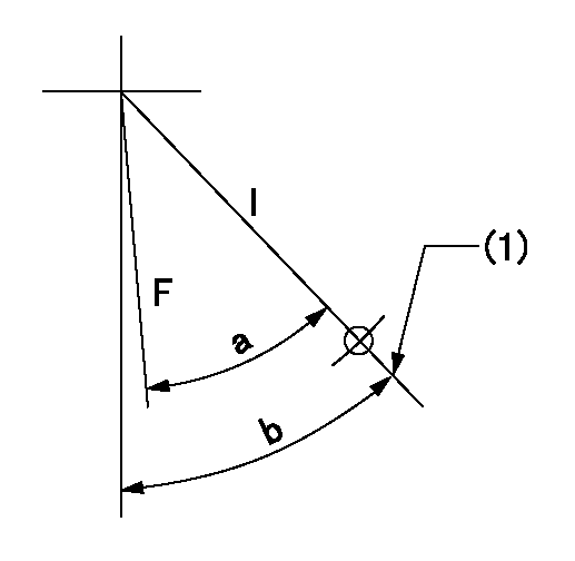
F:Full speed
I:Idle
(1)Stopper bolt set position 'H'
----------
----------
a=34deg+-3deg b=34deg+-5deg
----------
----------
a=34deg+-3deg b=34deg+-5deg
Stop lever angle
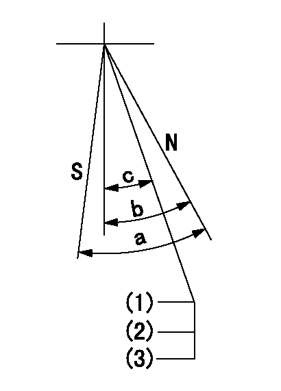
N:Pump normal
S:Stop the pump.
(1)Engine normal
(2)Set the stopper bolt at rack = aa (apply red paint after setting).
(3)(At delivery)
----------
aa=17+-0.1mm
----------
a=40deg+-5deg b=40deg+-5deg c=(35deg)
----------
aa=17+-0.1mm
----------
a=40deg+-5deg b=40deg+-5deg c=(35deg)
Timing setting

(1)Pump vertical direction
(2)Position of gear's standard threaded hole at No 1 cylinder's beginning of injection
(3)-
(4)-
----------
----------
a=(70deg)
----------
----------
a=(70deg)
Information:
Start By:a. remove timing gear cover
Do not disconnect the air line from the air compressor governor until the air pressure is zero.
1. Loosen the bleed valves, and release the air pressure in the air tank. 2. Disconnect the lines from air compressor (1), and remove the air compressor. 3. Remove sleeve (2) from air compressor drive gear (3). 4. Remove the nut and washer that holds the air compressor drive gear to the air compressor. Use tooling (A) to remove air compressor drive gear (3) from the air compressor. 5. Remove nuts (4) and plate (5). Remove gear assembly (6) from the shaft. 6. If damaged, remove bearing (7) from gear assembly (6) with tooling (B) and a press. 7. Remove three nuts (8) and the washers from the adapter assembly studs.
Typical Example8. Remove adapter assembly (9) from the timing gear plate. 9. Remove shaft (10), O-ring seal (11) and sleeve (12) from the adapter assembly.Install Air Compressor And Accessory Drive
1. Install sleeve (12) into the adapter assembly.2. Install shaft (10) and O-ring seal (11) on the adapter assembly. 3. Put adapter assembly (9) in position on the timing gear plate. Fasten it with the three nuts and washers. 4. Install the bearing in gear assembly (6) with tooling (A) and a press. Install the bearing until it is 1.5 0.5 mm (.06 .02 in.) below the surface of the gear as shown. 5. Put gear assembly (6) in position on the shaft.6. Put plate (5) in position, and install three nuts (4) to hold it. 7. Put air compressor drive gear (3) in position on the air compressor shaft, and install the washer and nut (13). Tighten the nut to a torque of 200 25 N m (150 18 lb.ft.). Tap the gear with a hammer and tighten nut (13) again to a torque of 200 25 N m (150 18 lb.ft.). 8. Install sleeve (2) on gear (3). 9. Put a gasket in position on air compressor (1) and install the air compressor on the timing cover plate.End By:a. install timing gear cover
Have questions with 101601-5467?
Group cross 101601-5467 ZEXEL
Hino
Hino
101601-5467
9 400 614 613
220006213A
INJECTION-PUMP ASSEMBLY
W06E
W06E