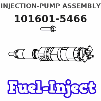
Information injection-pump assembly
ZEXEL
101601-5466
1016015466
Rating:
Service parts 101601-5466 INJECTION-PUMP ASSEMBLY:
1.
_
6.
COUPLING PLATE
7.
COUPLING PLATE
8.
_
9.
_
11.
Nozzle and Holder
12.
Open Pre:MPa(Kqf/cm2)
19.6(200)
15.
NOZZLE SET
Cross reference number
ZEXEL
101601-5466
1016015466
Zexel num
Bosch num
Firm num
Name
101601-5466
INJECTION-PUMP ASSEMBLY
14BE PE6A PE
14BE PE6A PE
Calibration Data:
Adjustment conditions
Test oil
1404 Test oil ISO4113 or {SAEJ967d}
1404 Test oil ISO4113 or {SAEJ967d}
Test oil temperature
degC
40
40
45
Nozzle and nozzle holder
105780-8210
Nozzle
105780-0070
Bosch type code
DN12SD12T-1
Nozzle holder
105780-2080
Bosch type code
EF8511/9
Opening pressure
MPa
17.2
Opening pressure
kgf/cm2
175
Injection pipe
Outer diameter - inner diameter - length (mm) mm 6-2-600
Outer diameter - inner diameter - length (mm) mm 6-2-600
Overflow valve
134424-0920
Overflow valve opening pressure
kPa
162
147
177
Overflow valve opening pressure
kgf/cm2
1.65
1.5
1.8
Tester oil delivery pressure
kPa
157
157
157
Tester oil delivery pressure
kgf/cm2
1.6
1.6
1.6
Direction of rotation (viewed from drive side)
Right R
Right R
Injection timing adjustment
Direction of rotation (viewed from drive side)
Right R
Right R
Injection order
1-4-2-6-
3-5
Pre-stroke
mm
3.45
3.42
3.48
Beginning of injection position
Drive side NO.1
Drive side NO.1
Difference between angles 1
Cal 1-4 deg. 60 59.75 60.25
Cal 1-4 deg. 60 59.75 60.25
Difference between angles 2
Cyl.1-2 deg. 120 119.75 120.25
Cyl.1-2 deg. 120 119.75 120.25
Difference between angles 3
Cal 1-6 deg. 180 179.75 180.25
Cal 1-6 deg. 180 179.75 180.25
Difference between angles 4
Cal 1-3 deg. 240 239.75 240.25
Cal 1-3 deg. 240 239.75 240.25
Difference between angles 5
Cal 1-5 deg. 300 299.75 300.25
Cal 1-5 deg. 300 299.75 300.25
Injection quantity adjustment
Adjusting point
-
Rack position
10.7
Pump speed
r/min
900
900
900
Average injection quantity
mm3/st.
63.7
61.7
65.7
Max. variation between cylinders
%
0
-3.5
3.5
Basic
*
Fixing the rack
*
Standard for adjustment of the maximum variation between cylinders
*
Injection quantity adjustment_02
Adjusting point
H
Rack position
9.3+-0.5
Pump speed
r/min
250
250
250
Each cylinder's injection qty
mm3/st.
17
16
18
Fixing the rack
*
Standard for adjustment of the maximum variation between cylinders
*
Injection quantity adjustment_03
Adjusting point
A
Rack position
R1(10.7)
Pump speed
r/min
900
900
900
Average injection quantity
mm3/st.
63.7
62.7
64.7
Basic
*
Fixing the lever
*
Injection quantity adjustment_04
Adjusting point
B
Rack position
R1+0.05
Pump speed
r/min
1500
1500
1500
Average injection quantity
mm3/st.
61.7
57.7
65.7
Fixing the lever
*
Injection quantity adjustment_05
Adjusting point
C
Rack position
R1-0.4
Pump speed
r/min
600
600
600
Average injection quantity
mm3/st.
55.3
51.3
59.3
Fixing the lever
*
Injection quantity adjustment_06
Adjusting point
I
Rack position
-
Pump speed
r/min
100
100
100
Average injection quantity
mm3/st.
122
122
132
Fixing the lever
*
Rack limit
*
Timer adjustment
Pump speed
r/min
960--
Advance angle
deg.
0
0
0
Load
1/4
Remarks
Start
Start
Timer adjustment_02
Pump speed
r/min
910
Advance angle
deg.
0.3
Load
1/4
Timer adjustment_03
Pump speed
r/min
1010
Advance angle
deg.
1
0.7
1.3
Load
4/4
Timer adjustment_04
Pump speed
r/min
1210
Advance angle
deg.
1
0.7
1.3
Load
3/4
Timer adjustment_05
Pump speed
r/min
1510
Advance angle
deg.
6
5.7
6.3
Load
4/4
Remarks
Finish
Finish
Test data Ex:
Governor adjustment
N:Pump speed
R:Rack position (mm)
(1)Torque cam stamping: T1
(2)Tolerance for racks not indicated: +-0.05mm.
(3)RACK LIMIT
----------
T1=E73
----------
----------
T1=E73
----------
Speed control lever angle
F:Full speed
I:Idle
(1)Use the hole at R = aa
(2)Stopper bolt set position 'H'
----------
aa=55mm
----------
a=34deg+-3deg b=34deg+-5deg
----------
aa=55mm
----------
a=34deg+-3deg b=34deg+-5deg
Stop lever angle
N:Pump normal
S:Stop the pump.
(1)Engine normal
(2)Set the stopper bolt at rack = aa (apply red paint after setting).
----------
aa=17+-0.1mm
----------
a=(35deg) b=40deg+-5deg c=40deg+-5deg
----------
aa=17+-0.1mm
----------
a=(35deg) b=40deg+-5deg c=40deg+-5deg
Timing setting

(1)Pump vertical direction
(2)Position of gear's standard threaded hole at No 1 cylinder's beginning of injection
(3)-
(4)-
----------
----------
a=(70deg)
----------
----------
a=(70deg)
Information:
Start By:a. remove timing gear coverb. remove fuel injection pump housing and rack actuator package 1. Remove four bolts (2), plate (3) and idler gear (1). 2. If the camshaft is not going to be removed, use tooling (A) to remove camshaft gear (4).
Do not turn the crankshaft with the camshaft gear removed. Damage can be caused to the pistons and valves, or both.
3. Remove bolts (5) that hold timing gear plate (6) to the cylinder block.4. Remove timing gear plate (6). 5. Use tooling (B) to remove the bearing from the idler gear. The following steps are for the installation of the timing gears and plate.6. Install a new gasket on the timing gear plate.7. Put timing gear plate (6) in position on the cylinder block, and install the bolts that hold the timing gear plate to the cylinder block.8. Heat camshaft gear (4) to a maximum temperature of 315° C (600° F), and install it on the camshaft.9. Use tooling (B), and install the bearing in the idler gear. Set the gear on the front face, (face with timing marks). Drive the bearing from the rear face toward the front face of the gear. Install the bearing to a depth of 1.5 0.5 mm (.06 .02 in.) below the rear face of the idler gear.10. Install the idler gear, plate and bolts. Be sure No. 1 cylinder is at top center on the compression stroke. Install the idler gear so "V" mark (7) on the idler gear is in alignment with the "V" mark on the crankshaft gear. "K" marks (8) of the camshaft gear can be seen at the outer edges of the idler gear.End By:a. install fuel injection pump housing and rack actuator packageb. install timing gear cover
Have questions with 101601-5466?
Group cross 101601-5466 ZEXEL
Hino
101601-5466
INJECTION-PUMP ASSEMBLY