Information injection-pump assembly
ZEXEL
101601-5381
1016015381
HINO
220005970A
220005970a

Rating:
Service parts 101601-5381 INJECTION-PUMP ASSEMBLY:
1.
_
6.
COUPLING PLATE
7.
COUPLING PLATE
8.
_
9.
_
11.
Nozzle and Holder
12.
Open Pre:MPa(Kqf/cm2)
21.6(220)
15.
NOZZLE SET
Cross reference number
ZEXEL
101601-5381
1016015381
HINO
220005970A
220005970a
Zexel num
Bosch num
Firm num
Name
101601-5381
220005970A HINO
INJECTION-PUMP ASSEMBLY
W06D * K
W06D * K
Calibration Data:
Adjustment conditions
Test oil
1404 Test oil ISO4113 or {SAEJ967d}
1404 Test oil ISO4113 or {SAEJ967d}
Test oil temperature
degC
40
40
45
Nozzle and nozzle holder
105780-8140
Bosch type code
EF8511/9A
Nozzle
105780-0000
Bosch type code
DN12SD12T
Nozzle holder
105780-2080
Bosch type code
EF8511/9
Opening pressure
MPa
17.2
Opening pressure
kgf/cm2
175
Injection pipe
Outer diameter - inner diameter - length (mm) mm 6-2-600
Outer diameter - inner diameter - length (mm) mm 6-2-600
Overflow valve
131424-5720
Overflow valve opening pressure
kPa
255
221
289
Overflow valve opening pressure
kgf/cm2
2.6
2.25
2.95
Tester oil delivery pressure
kPa
157
157
157
Tester oil delivery pressure
kgf/cm2
1.6
1.6
1.6
Direction of rotation (viewed from drive side)
Right R
Right R
Injection timing adjustment
Direction of rotation (viewed from drive side)
Right R
Right R
Injection order
1-4-2-6-
3-5
Pre-stroke
mm
3.1
3.07
3.13
Beginning of injection position
Drive side NO.1
Drive side NO.1
Difference between angles 1
Cal 1-4 deg. 60 59.75 60.25
Cal 1-4 deg. 60 59.75 60.25
Difference between angles 2
Cyl.1-2 deg. 120 119.75 120.25
Cyl.1-2 deg. 120 119.75 120.25
Difference between angles 3
Cal 1-6 deg. 180 179.75 180.25
Cal 1-6 deg. 180 179.75 180.25
Difference between angles 4
Cal 1-3 deg. 240 239.75 240.25
Cal 1-3 deg. 240 239.75 240.25
Difference between angles 5
Cal 1-5 deg. 300 299.75 300.25
Cal 1-5 deg. 300 299.75 300.25
Injection quantity adjustment
Adjusting point
-
Rack position
8.7
Pump speed
r/min
1000
1000
1000
Average injection quantity
mm3/st.
46.6
44.6
48.6
Max. variation between cylinders
%
0
-3.5
3.5
Basic
*
Fixing the rack
*
Standard for adjustment of the maximum variation between cylinders
*
Injection quantity adjustment_02
Adjusting point
H
Rack position
8+-0.5
Pump speed
r/min
250
250
250
Average injection quantity
mm3/st.
8
6.5
9.5
Max. variation between cylinders
%
0
-10
10
Fixing the rack
*
Standard for adjustment of the maximum variation between cylinders
*
Injection quantity adjustment_03
Adjusting point
A
Rack position
R1(8.7)
Pump speed
r/min
1000
1000
1000
Average injection quantity
mm3/st.
46.6
45.6
47.6
Basic
*
Fixing the lever
*
Injection quantity adjustment_04
Adjusting point
B
Rack position
R1-0.3
Pump speed
r/min
1600
1600
1600
Average injection quantity
mm3/st.
45.2
43.2
47.2
Fixing the lever
*
Injection quantity adjustment_05
Adjusting point
C
Rack position
R1+0.2
Pump speed
r/min
1300
1300
1300
Average injection quantity
mm3/st.
52
50
54
Fixing the lever
*
Injection quantity adjustment_06
Adjusting point
D
Rack position
R1-0.15
Pump speed
r/min
650
650
650
Average injection quantity
mm3/st.
38
36
40
Fixing the lever
*
Injection quantity adjustment_07
Adjusting point
E
Rack position
R1+0.35
Pump speed
r/min
400
400
400
Average injection quantity
mm3/st.
28
24
32
Fixing the lever
*
Timer adjustment
Pump speed
r/min
1300+50
Advance angle
deg.
0
0
0
Remarks
Start
Start
Timer adjustment_02
Pump speed
r/min
1600
Advance angle
deg.
3.5
3.2
3.8
Remarks
Finish
Finish
Test data Ex:
Governor adjustment
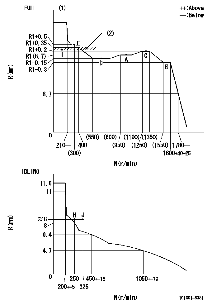
N:Pump speed
R:Rack position (mm)
(1)Torque cam stamping: T1
(2)RACK LIMIT: RAL
----------
T1=A76 RAL=(R1+0.2)+0.2mm
----------
----------
T1=A76 RAL=(R1+0.2)+0.2mm
----------
Speed control lever angle

F:Full speed
I:Idle
(1)Stopper bolt set position 'H'
----------
----------
a=33deg+-3deg b=34deg+-5deg
----------
----------
a=33deg+-3deg b=34deg+-5deg
Stop lever angle

N:Pump normal
S:Stop the pump.
----------
----------
a=40deg+-5deg b=40deg+-5deg
----------
----------
a=40deg+-5deg b=40deg+-5deg
Timing setting

(1)Pump vertical direction
(2)Position of gear's standard threaded hole at No 1 cylinder's beginning of injection
(3)-
(4)-
----------
----------
a=(70deg)
----------
----------
a=(70deg)
Information:
37. Remove races (70) and (72) and bearing (71) from the camshaft in the fuel injection pump housing. Assemble Governor
1. Put the fuel injection pump housing in position on tool (A). Install race (3), bearing (2) and race (1) on the end of the camshaft in the fuel injection pump housing. 2. Put flyweights (5) in position on carrier assembly (4), and install dowels (6) to hold the flyweights in place. The flyweights must move freely on the dowels and have 0.010 to 0.230 mm (.0004 to .0090 in) end play. 3. Install governor shaft (7) on carrier assembly (4). 4. Install dowel (8) in governor shaft (7), and slide carrier assembly (4) down on the governor shaft until dowel (8) fits into the slot in the carrier assembly.5. Install carrier assembly (4) on the end of the camshaft. 6. Install race (12), bearing (11), race (10) and ring (9) on riser (13). 7. Install riser (13) and spring (14), if equipped, on the governor shaft. 8. Install spool (18) and ring (19) on seat (17), and use tool (B) to install ring (20) to hold them in position.9. Install seat (17) on spring (16) and spring (16) on shield (15). 10. Install dashpot assembly (21) on the governor shaft. 11. Install ring (22) in the groove on the governor shaft. Install sleeve (23), spring (25), the sleeve and bearing (24) on the governor shaft. 12. Use tool (C) to hold spring (25) under compression, and install the ring in the groove on the governor shaft. 13. Install O-ring seal (26) on sleeve (27). Install piston (29) and sleeve (27) in the governor servo as shown.14. Install valve (28) in the governor servo as shown. 15. Install lockring (33) in the groove near the center of valve (28). Put sleeve (34), spring (broken link spring) (35) and seat (36) in position on valve (28), and install lockring (37) to hold them in place. 16. Put governor servo (30) in position on the fuel injection pump housing with piston (29) engaged over the rack. Make sure the lever is engaged in the (slot) groove of riser (13). 17. If dowel (43) was removed, install it in block (44) 31 0.5 mm (1.22 .02 in) above the outside surface of the block.18. Install bolt (45) in block (44) and spring (38) on bolt (45).19. Install stop screw (40) and the locknut on collar (42). Install power setting screw (41) and the locknut on the collar.20. Install collar (42) on bolt (45). Make an alignment of the hole in the collar with the notch in bolt (45), and install bolt (39). 21. If the dowels that align block (44) with the front governor housing were removed, install them 4.0 0.5 mm (.16 .02 in) above the outside surface of the front governor housing.22. Put block (44) in position on the front governor housing with the holes in the block in alignment with dowels in the front governor
1. Put the fuel injection pump housing in position on tool (A). Install race (3), bearing (2) and race (1) on the end of the camshaft in the fuel injection pump housing. 2. Put flyweights (5) in position on carrier assembly (4), and install dowels (6) to hold the flyweights in place. The flyweights must move freely on the dowels and have 0.010 to 0.230 mm (.0004 to .0090 in) end play. 3. Install governor shaft (7) on carrier assembly (4). 4. Install dowel (8) in governor shaft (7), and slide carrier assembly (4) down on the governor shaft until dowel (8) fits into the slot in the carrier assembly.5. Install carrier assembly (4) on the end of the camshaft. 6. Install race (12), bearing (11), race (10) and ring (9) on riser (13). 7. Install riser (13) and spring (14), if equipped, on the governor shaft. 8. Install spool (18) and ring (19) on seat (17), and use tool (B) to install ring (20) to hold them in position.9. Install seat (17) on spring (16) and spring (16) on shield (15). 10. Install dashpot assembly (21) on the governor shaft. 11. Install ring (22) in the groove on the governor shaft. Install sleeve (23), spring (25), the sleeve and bearing (24) on the governor shaft. 12. Use tool (C) to hold spring (25) under compression, and install the ring in the groove on the governor shaft. 13. Install O-ring seal (26) on sleeve (27). Install piston (29) and sleeve (27) in the governor servo as shown.14. Install valve (28) in the governor servo as shown. 15. Install lockring (33) in the groove near the center of valve (28). Put sleeve (34), spring (broken link spring) (35) and seat (36) in position on valve (28), and install lockring (37) to hold them in place. 16. Put governor servo (30) in position on the fuel injection pump housing with piston (29) engaged over the rack. Make sure the lever is engaged in the (slot) groove of riser (13). 17. If dowel (43) was removed, install it in block (44) 31 0.5 mm (1.22 .02 in) above the outside surface of the block.18. Install bolt (45) in block (44) and spring (38) on bolt (45).19. Install stop screw (40) and the locknut on collar (42). Install power setting screw (41) and the locknut on the collar.20. Install collar (42) on bolt (45). Make an alignment of the hole in the collar with the notch in bolt (45), and install bolt (39). 21. If the dowels that align block (44) with the front governor housing were removed, install them 4.0 0.5 mm (.16 .02 in) above the outside surface of the front governor housing.22. Put block (44) in position on the front governor housing with the holes in the block in alignment with dowels in the front governor
Have questions with 101601-5381?
Group cross 101601-5381 ZEXEL
Hino
Hino
Hino
Hino
Hino
Hino
101601-5381
220005970A
INJECTION-PUMP ASSEMBLY
W06D
W06D