Information injection-pump assembly
ZEXEL
101601-5370
1016015370
HINO
220005940A
220005940a

Rating:
Cross reference number
ZEXEL
101601-5370
1016015370
HINO
220005940A
220005940a
Zexel num
Bosch num
Firm num
Name
Calibration Data:
Adjustment conditions
Test oil
1404 Test oil ISO4113 or {SAEJ967d}
1404 Test oil ISO4113 or {SAEJ967d}
Test oil temperature
degC
40
40
45
Nozzle and nozzle holder
105780-8140
Bosch type code
EF8511/9A
Nozzle
105780-0000
Bosch type code
DN12SD12T
Nozzle holder
105780-2080
Bosch type code
EF8511/9
Opening pressure
MPa
17.2
Opening pressure
kgf/cm2
175
Injection pipe
Outer diameter - inner diameter - length (mm) mm 6-2-600
Outer diameter - inner diameter - length (mm) mm 6-2-600
Overflow valve
131424-5720
Overflow valve opening pressure
kPa
255
221
289
Overflow valve opening pressure
kgf/cm2
2.6
2.25
2.95
Tester oil delivery pressure
kPa
157
157
157
Tester oil delivery pressure
kgf/cm2
1.6
1.6
1.6
Direction of rotation (viewed from drive side)
Right R
Right R
Injection timing adjustment
Direction of rotation (viewed from drive side)
Right R
Right R
Injection order
1-4-2-6-
3-5
Pre-stroke
mm
3.1
3.07
3.13
Beginning of injection position
Drive side NO.1
Drive side NO.1
Difference between angles 1
Cal 1-4 deg. 60 59.75 60.25
Cal 1-4 deg. 60 59.75 60.25
Difference between angles 2
Cyl.1-2 deg. 120 119.75 120.25
Cyl.1-2 deg. 120 119.75 120.25
Difference between angles 3
Cal 1-6 deg. 180 179.75 180.25
Cal 1-6 deg. 180 179.75 180.25
Difference between angles 4
Cal 1-3 deg. 240 239.75 240.25
Cal 1-3 deg. 240 239.75 240.25
Difference between angles 5
Cal 1-5 deg. 300 299.75 300.25
Cal 1-5 deg. 300 299.75 300.25
Injection quantity adjustment
Adjusting point
-
Rack position
9.6
Pump speed
r/min
900
900
900
Average injection quantity
mm3/st.
57.9
55.9
59.9
Max. variation between cylinders
%
0
-3.5
3.5
Basic
*
Fixing the rack
*
Standard for adjustment of the maximum variation between cylinders
*
Injection quantity adjustment_02
Adjusting point
H
Rack position
7.8+-0.5
Pump speed
r/min
250
250
250
Average injection quantity
mm3/st.
5.3
3.8
6.8
Max. variation between cylinders
%
0
-10
10
Fixing the rack
*
Standard for adjustment of the maximum variation between cylinders
*
Injection quantity adjustment_03
Adjusting point
A
Rack position
R1(9.6)
Pump speed
r/min
900
900
900
Average injection quantity
mm3/st.
57.9
56.9
58.9
Basic
*
Fixing the lever
*
Injection quantity adjustment_04
Adjusting point
B
Rack position
R1(9.6)
Pump speed
r/min
1500
1500
1500
Average injection quantity
mm3/st.
63.9
59.9
67.9
Fixing the lever
*
Injection quantity adjustment_05
Adjusting point
C
Rack position
R1-0.25
Pump speed
r/min
600
600
600
Average injection quantity
mm3/st.
40.3
36.3
44.3
Fixing the lever
*
Injection quantity adjustment_06
Adjusting point
D
Rack position
R1(9.6)
Pump speed
r/min
1200
1200
1200
Average injection quantity
mm3/st.
63.7
59.7
67.7
Fixing the lever
*
Injection quantity adjustment_07
Adjusting point
E
Rack position
R1+0.45
Pump speed
r/min
400
400
400
Average injection quantity
mm3/st.
39.9
35.9
43.9
Fixing the lever
*
Injection quantity adjustment_08
Adjusting point
I
Rack position
14.5+-0.
5
Pump speed
r/min
100
100
100
Average injection quantity
mm3/st.
108
108
118
Fixing the lever
*
Rack limit
*
Timer adjustment
Pump speed
r/min
1200+50
Advance angle
deg.
0
0
0
Remarks
Start
Start
Timer adjustment_02
Pump speed
r/min
1500
Advance angle
deg.
4.5
4.2
4.8
Remarks
Finish
Finish
Test data Ex:
Governor adjustment
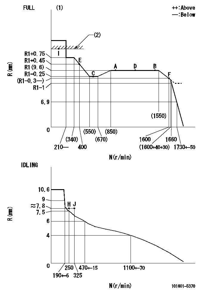
N:Pump speed
R:Rack position (mm)
(1)Torque cam stamping: T1
(2)RACK LIMIT
----------
T1=C02
----------
----------
T1=C02
----------
Speed control lever angle
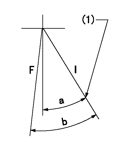
F:Full speed
I:Idle
(1)Stopper bolt set position 'H'
----------
----------
a=37deg+-5deg b=(40deg)+-3deg
----------
----------
a=37deg+-5deg b=(40deg)+-3deg
Stop lever angle

N:Pump normal
S:Stop the pump.
----------
----------
a=40deg+-5deg b=40deg+-5deg
----------
----------
a=40deg+-5deg b=40deg+-5deg
0000001501 AIR CYLINDER

(A): Speed lever
(B): Set bolt
(C): air cylinder
(D): nut
(E): fix
1. Air cylinder adjustment procedure
(1)With the speed lever in the idling position, temporarily set the clearance between speed lever (A) and set bolt (B) at approximately L1.
(2)Set the speed to N1 and supply positive pressure P1 to the air cylinder (C).
(3)Gradually push set bolt (B) out (approximately L2) and tighten nut (D) where the speed is N2 and the rack position is Ra.
(4)Apply positive pressure P1 several times.
(5)Confirm that the lever returns to the idle position at positive pressure P2.
(6)Also, confirm that the rack position is Rb at air pressure P1.
----------
L1=5mm L2=1.4mm Ra=7.3+-0.1mm Rb=7.3+-0.1mm N1=475r/min N2=475r/min P1=392+98kPa(4+1kgf/cm2) P2=0kPa(0kgf/cm2)
----------
----------
L1=5mm L2=1.4mm Ra=7.3+-0.1mm Rb=7.3+-0.1mm N1=475r/min N2=475r/min P1=392+98kPa(4+1kgf/cm2) P2=0kPa(0kgf/cm2)
----------
Timing setting

(1)Pump vertical direction
(2)Position of gear's standard threaded hole at No 1 cylinder's beginning of injection
(3)-
(4)-
----------
----------
a=(70deg)
----------
----------
a=(70deg)
Information:
1. Remove fuel line (1) from the fuel transfer pump.2. Put caps in the fuel line openings to prevent fuel system contamination.3. Remove bolts (2), and remove fuel transfer pump (3). Check the condition of the O-ring seal on the fuel transfer pump. If necessary, make a replacement.Install Fuel Transfer Pump
1. Be sure O-ring seal (1) is in position on the fuel transfer pump. Put clean engine oil on the O-ring seal.2. Put fuel transfer pump (2) in position, and install the bolts that hold it in place.3. Remove the caps from the fuel line openings, and install fuel line (3).4. Prime the fuel system. See the Maintenance Guide for this procedure.Disassemble Fuel Transfer Pump
Start By:a. remove fuel transfer pump 1. Remove seal (1) from the fuel transfer pump.
Cover (2) is under spring tension. Remove the bolts that hold cover (2) slowly to prevent injury.
2. Remove bolts (3) and cover (2) from the housing. 3. Remove seals (4) and valve (5) from cover (2). 4. Remove spring (6) from the piston.
Mark the orientation of valve (8) as to its location in the housing.
5. Remove washer (7), valve (8) and the seal from the housing. 6. Remove piston (9) and sleeve (10) from the housing. 7. Remove seal (11) from sleeve (12). 8. Remove guide and tappet assembly (13) from the housing. 9. Remove seal (14) from guide (15).
If tappet (17) or the guide are damaged or worn, they must be replaced as a unit.
10. Remove ring (16) from tappet (17) and the tappet from guide (15). 11. Remove the bolts and cover (18) from the housing. 12. Remove seal (19) from cover (18). 13. Remove valve (20) from the housing if necessary. Assemble Fuel Transfer Pump
1. Install valve (2) in housing (1) as shown. 2. Put clean fuel on seal (4), and install it on cover (3).3. Install cover (3) on the housing.
The tappet and guide must be serviced as a unit.
4. Install tappet (6) in guide (5). Install ring (7) on tappet (6) to hold the tappet in the guide. 5. Put clean fuel on seal (8), and install it on guide and tappet assembly (9).6. Install guide and tappet assembly (9) in the housing as shown. 7. Put clean fuel on seal (10), and install it on sleeve (11).8. Install sleeve (11) in the housing. 9. Install piston (12) in the housing. 10. Install seal valve (14) and washer (13) in the housing as shown. Be sure valve (14) is the correct position in the housing. 11. Install spring (15) in the piston. 12. Install valve (18) in cover (16) as shown.13. Put clean fuel on seals (17), and put them in position on cover (16).14. Install cover (16) on the housing. 15. Put seal (19) in position on the fuel transfer pump.16. Install the fuel transfer pump on the fuel injection pump housing.End By:a. install fuel transfer pump