Information injection-pump assembly
ZEXEL
101601-5300
1016015300
Rating:
Service parts 101601-5300 INJECTION-PUMP ASSEMBLY:
1.
_
6.
COUPLING PLATE
7.
COUPLING PLATE
8.
_
9.
_
11.
Nozzle and Holder
12.
Open Pre:MPa(Kqf/cm2)
21.6(220)
15.
NOZZLE SET
Cross reference number
ZEXEL
101601-5300
1016015300
Zexel num
Bosch num
Firm num
Name
101601-5300
INJECTION-PUMP ASSEMBLY
Calibration Data:
Adjustment conditions
Test oil
1404 Test oil ISO4113 or {SAEJ967d}
1404 Test oil ISO4113 or {SAEJ967d}
Test oil temperature
degC
40
40
45
Nozzle and nozzle holder
105780-8140
Bosch type code
EF8511/9A
Nozzle
105780-0000
Bosch type code
DN12SD12T
Nozzle holder
105780-2080
Bosch type code
EF8511/9
Opening pressure
MPa
17.2
Opening pressure
kgf/cm2
175
Injection pipe
Outer diameter - inner diameter - length (mm) mm 6-2-600
Outer diameter - inner diameter - length (mm) mm 6-2-600
Overflow valve
131424-5720
Overflow valve opening pressure
kPa
255
221
289
Overflow valve opening pressure
kgf/cm2
2.6
2.25
2.95
Tester oil delivery pressure
kPa
157
157
157
Tester oil delivery pressure
kgf/cm2
1.6
1.6
1.6
Direction of rotation (viewed from drive side)
Right R
Right R
Injection timing adjustment
Direction of rotation (viewed from drive side)
Right R
Right R
Injection order
1-4-2-6-
3-5
Pre-stroke
mm
3.1
3.07
3.13
Beginning of injection position
Drive side NO.1
Drive side NO.1
Difference between angles 1
Cal 1-4 deg. 60 59.75 60.25
Cal 1-4 deg. 60 59.75 60.25
Difference between angles 2
Cyl.1-2 deg. 120 119.75 120.25
Cyl.1-2 deg. 120 119.75 120.25
Difference between angles 3
Cal 1-6 deg. 180 179.75 180.25
Cal 1-6 deg. 180 179.75 180.25
Difference between angles 4
Cal 1-3 deg. 240 239.75 240.25
Cal 1-3 deg. 240 239.75 240.25
Difference between angles 5
Cal 1-5 deg. 300 299.75 300.25
Cal 1-5 deg. 300 299.75 300.25
Injection quantity adjustment
Adjusting point
-
Rack position
8.7
Pump speed
r/min
1000
1000
1000
Average injection quantity
mm3/st.
46.6
44.6
48.6
Max. variation between cylinders
%
0
-3.5
3.5
Basic
*
Fixing the rack
*
Standard for adjustment of the maximum variation between cylinders
*
Injection quantity adjustment_02
Adjusting point
H
Rack position
8+-0.5
Pump speed
r/min
250
250
250
Average injection quantity
mm3/st.
8
6.5
9.5
Max. variation between cylinders
%
0
-10
10
Fixing the rack
*
Standard for adjustment of the maximum variation between cylinders
*
Injection quantity adjustment_03
Adjusting point
A
Rack position
R1(8.7)
Pump speed
r/min
1000
1000
1000
Average injection quantity
mm3/st.
46.6
45.6
47.6
Basic
*
Fixing the lever
*
Injection quantity adjustment_04
Adjusting point
B
Rack position
R1-0.3
Pump speed
r/min
1600
1600
1600
Average injection quantity
mm3/st.
45.2
43.2
47.2
Fixing the lever
*
Injection quantity adjustment_05
Adjusting point
C
Rack position
R1+0.2
Pump speed
r/min
1300
1300
1300
Average injection quantity
mm3/st.
52
50
54
Fixing the lever
*
Injection quantity adjustment_06
Adjusting point
D
Rack position
R1-0.15
Pump speed
r/min
650
650
650
Average injection quantity
mm3/st.
38
36
40
Fixing the lever
*
Injection quantity adjustment_07
Adjusting point
I
Rack position
13.5+-0.
5
Pump speed
r/min
100
100
100
Average injection quantity
mm3/st.
95
95
105
Fixing the lever
*
Rack limit
*
Injection quantity adjustment_08
Adjusting point
E
Rack position
R1+0.35
Pump speed
r/min
400
400
400
Average injection quantity
mm3/st.
28
24
32
Fixing the lever
*
Timer adjustment
Pump speed
r/min
1300+50
Advance angle
deg.
0
0
0
Remarks
Start
Start
Timer adjustment_02
Pump speed
r/min
1600
Advance angle
deg.
3.5
3.2
3.8
Remarks
Finish
Finish
Test data Ex:
Governor adjustment
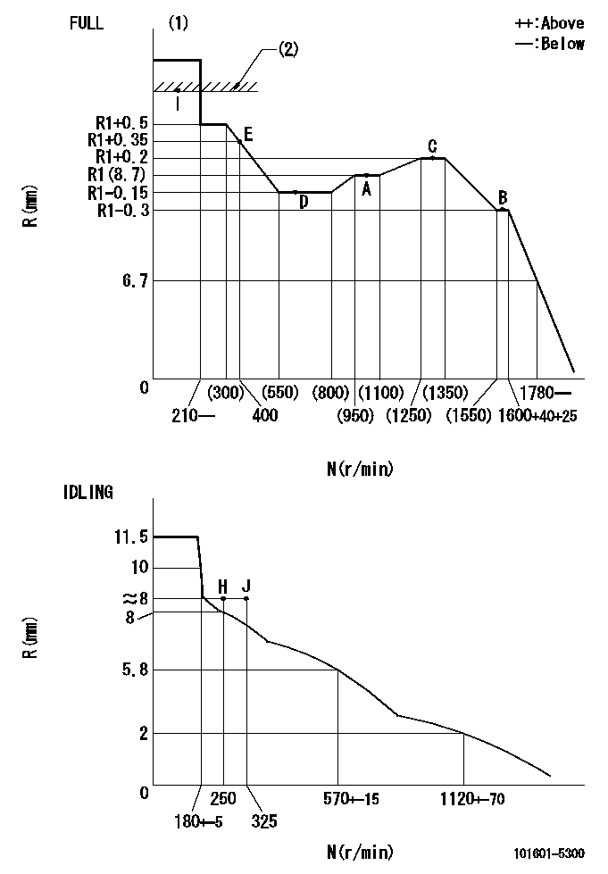
N:Pump speed
R:Rack position (mm)
(1)Torque cam stamping: T1
(2)RACK LIMIT
----------
T1=C46
----------
----------
T1=C46
----------
Speed control lever angle
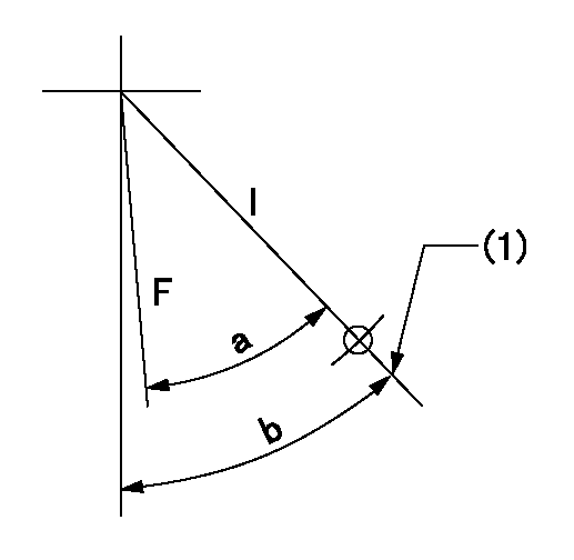
F:Full speed
I:Idle
(1)Stopper bolt set position 'H'
----------
----------
a=(45deg)+-3deg b=46deg+-5deg
----------
----------
a=(45deg)+-3deg b=46deg+-5deg
Stop lever angle

N:Pump normal
S:Stop the pump.
----------
----------
a=20deg+-5deg b=40deg+-5deg
----------
----------
a=20deg+-5deg b=40deg+-5deg
Timing setting

(1)Pump vertical direction
(2)Position of gear's standard threaded hole at No 1 cylinder's beginning of injection
(3)-
(4)-
----------
----------
a=(70deg)
----------
----------
a=(70deg)
Information:
Recommended Procedure With Chassis Dynamometer
Possible Causes/Corrections
Minor Operating FaultsTo help identify a problem before a more involved troubleshooting procedure is started, follow the procedure given in the "Primary Engine Checks" section. Fuel Ratio Control Out Of Adjustment Or DefectiveFollow the procedure in the Testing and Adjusting Section of this Service Manual. Check Engine PerformanceDo a Power Analysis Report (PAR), Level II, to check engine performance. See Special Instruction, Form No. SEHS8025 and SEHS7886 for the tooling and procedures to use. Be sure to make a record of the temperatures for inlet air, fuel (at filter base), lubricating oil and coolant. Make the necessary adjustments or repairs to the engine if needed.At this point, the governor fuel settings should be verified. See the Testing and Adjusting Section of this Service Manual for the necessary procedures. Also, refer back to the information learned earlier (see "Owner/Operator Input" section) about the truck specifications and application and judge whether or not the engine is performing as expected or customer expectation is realistic.Recommended Procedure Without Chassis Dynamometer
Possible Causes/Corrections
Minor Operating FaultsTo help identify a problem before a more involved troubleshooting procedure is started, follow the procedure given in the "Primary Engine Checks" section. Fuel Ratio Control Out Of Adjustment Or DefectiveFollow the procedure in the Testing and Adjusting Section of this Service Manual. Fuel Injection Timing Not CorrectFollow the procedures in the Testing and Adjusting Section of this Service Manual. Check Engine PerformanceInstall the tooling and follow the procedure given in the Road Test section.At this point, the governor fuel settings should be verified. See the Testing and Adjusting Section of this Service Manual for the necessary procedures. Also, refer back to the information learned earlier (see "Owner/Operator Input" section) about the truck specifications and application and judge whether or not the engine is performing as expected or customer expectation is realistic.
Possible Causes/Corrections
Minor Operating FaultsTo help identify a problem before a more involved troubleshooting procedure is started, follow the procedure given in the "Primary Engine Checks" section. Fuel Ratio Control Out Of Adjustment Or DefectiveFollow the procedure in the Testing and Adjusting Section of this Service Manual. Check Engine PerformanceDo a Power Analysis Report (PAR), Level II, to check engine performance. See Special Instruction, Form No. SEHS8025 and SEHS7886 for the tooling and procedures to use. Be sure to make a record of the temperatures for inlet air, fuel (at filter base), lubricating oil and coolant. Make the necessary adjustments or repairs to the engine if needed.At this point, the governor fuel settings should be verified. See the Testing and Adjusting Section of this Service Manual for the necessary procedures. Also, refer back to the information learned earlier (see "Owner/Operator Input" section) about the truck specifications and application and judge whether or not the engine is performing as expected or customer expectation is realistic.Recommended Procedure Without Chassis Dynamometer
Possible Causes/Corrections
Minor Operating FaultsTo help identify a problem before a more involved troubleshooting procedure is started, follow the procedure given in the "Primary Engine Checks" section. Fuel Ratio Control Out Of Adjustment Or DefectiveFollow the procedure in the Testing and Adjusting Section of this Service Manual. Fuel Injection Timing Not CorrectFollow the procedures in the Testing and Adjusting Section of this Service Manual. Check Engine PerformanceInstall the tooling and follow the procedure given in the Road Test section.At this point, the governor fuel settings should be verified. See the Testing and Adjusting Section of this Service Manual for the necessary procedures. Also, refer back to the information learned earlier (see "Owner/Operator Input" section) about the truck specifications and application and judge whether or not the engine is performing as expected or customer expectation is realistic.
Have questions with 101601-5300?
Group cross 101601-5300 ZEXEL
101601-5300
INJECTION-PUMP ASSEMBLY