Information injection-pump assembly
BOSCH
9 400 614 606
9400614606
ZEXEL
101601-5262
1016015262
HINO
220005321A
220005321a
Rating:
Service parts 101601-5262 INJECTION-PUMP ASSEMBLY:
1.
_
6.
COUPLING PLATE
7.
COUPLING PLATE
8.
_
9.
_
11.
Nozzle and Holder
236001840A
12.
Open Pre:MPa(Kqf/cm2)
14.7(150)/19.6(200)
15.
NOZZLE SET
Cross reference number
BOSCH
9 400 614 606
9400614606
ZEXEL
101601-5262
1016015262
HINO
220005321A
220005321a
Zexel num
Bosch num
Firm num
Name
101601-5262
9 400 614 606
220005321A HINO
INJECTION-PUMP ASSEMBLY
W06E K
W06E K
Calibration Data:
Adjustment conditions
Test oil
1404 Test oil ISO4113 or {SAEJ967d}
1404 Test oil ISO4113 or {SAEJ967d}
Test oil temperature
degC
40
40
45
Nozzle and nozzle holder
105780-8140
Bosch type code
EF8511/9A
Nozzle
105780-0000
Bosch type code
DN12SD12T
Nozzle holder
105780-2080
Bosch type code
EF8511/9
Opening pressure
MPa
17.2
Opening pressure
kgf/cm2
175
Injection pipe
Outer diameter - inner diameter - length (mm) mm 6-2-600
Outer diameter - inner diameter - length (mm) mm 6-2-600
Overflow valve
131424-5720
Overflow valve opening pressure
kPa
255
221
289
Overflow valve opening pressure
kgf/cm2
2.6
2.25
2.95
Tester oil delivery pressure
kPa
157
157
157
Tester oil delivery pressure
kgf/cm2
1.6
1.6
1.6
Direction of rotation (viewed from drive side)
Right R
Right R
Injection timing adjustment
Direction of rotation (viewed from drive side)
Right R
Right R
Injection order
1-4-2-6-
3-5
Pre-stroke
mm
3.1
3.07
3.13
Beginning of injection position
Drive side NO.1
Drive side NO.1
Difference between angles 1
Cal 1-4 deg. 60 59.75 60.25
Cal 1-4 deg. 60 59.75 60.25
Difference between angles 2
Cyl.1-2 deg. 120 119.75 120.25
Cyl.1-2 deg. 120 119.75 120.25
Difference between angles 3
Cal 1-6 deg. 180 179.75 180.25
Cal 1-6 deg. 180 179.75 180.25
Difference between angles 4
Cal 1-3 deg. 240 239.75 240.25
Cal 1-3 deg. 240 239.75 240.25
Difference between angles 5
Cal 1-5 deg. 300 299.75 300.25
Cal 1-5 deg. 300 299.75 300.25
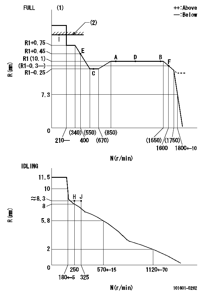
Injection quantity adjustment
Adjusting point
-
Rack position
10.1
Pump speed
r/min
900
900
900
Average injection quantity
mm3/st.
57.9
55.9
59.9
Max. variation between cylinders
%
0
-3.5
3.5
Basic
*
Fixing the rack
*
Standard for adjustment of the maximum variation between cylinders
*
Injection quantity adjustment_02
Adjusting point
H
Rack position
8.3+-0.5
Pump speed
r/min
250
250
250
Average injection quantity
mm3/st.
5.3
3.8
6.8
Max. variation between cylinders
%
0
-10
10
Fixing the rack
*
Standard for adjustment of the maximum variation between cylinders
*
Injection quantity adjustment_03
Adjusting point
A
Rack position
R1(10.1)
Pump speed
r/min
900
900
900
Average injection quantity
mm3/st.
57.9
56.9
58.9
Basic
*
Fixing the lever
*
Injection quantity adjustment_04
Adjusting point
B
Rack position
R1(10.1)
Pump speed
r/min
1500
1500
1500
Average injection quantity
mm3/st.
63.9
59.9
67.9
Fixing the lever
*
Injection quantity adjustment_05
Adjusting point
C
Rack position
R1-0.25
Pump speed
r/min
600
600
600
Average injection quantity
mm3/st.
40.3
36.3
44.3
Fixing the lever
*
Injection quantity adjustment_06
Adjusting point
D
Rack position
R1(10.1)
Pump speed
r/min
1200
1200
1200
Average injection quantity
mm3/st.
63.7
59.7
67.7
Fixing the lever
*
Injection quantity adjustment_07
Adjusting point
E
Rack position
R1+0.45
Pump speed
r/min
400
400
400
Average injection quantity
mm3/st.
39.9
35.9
43.9
Fixing the lever
*
Injection quantity adjustment_08
Adjusting point
I
Rack position
15+-0.5
Pump speed
r/min
100
100
100
Average injection quantity
mm3/st.
108
108
118
Fixing the lever
*
Rack limit
*
Timer adjustment
Pump speed
r/min
1330--
Advance angle
deg.
0
0
0
Load
3/4
Remarks
Start
Start
Timer adjustment_02
Pump speed
r/min
1280
Advance angle
deg.
0.3
Load
3/4
Timer adjustment_03
Pump speed
r/min
1500
Advance angle
deg.
4.5
4.2
4.8
Load
4/4
Remarks
Finish
Finish
Test data Ex:
Governor adjustment
N:Pump speed
R:Rack position (mm)
(1)Torque cam stamping: T1
(2)RACK LIMIT
----------
T1=C11
----------
----------
T1=C11
----------
Speed control lever angle
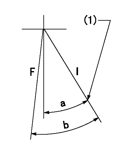
F:Full speed
I:Idle
(1)Stopper bolt set position 'H'
----------
----------
a=46deg+-5deg b=(47deg)+-3deg
----------
----------
a=46deg+-5deg b=(47deg)+-3deg
Stop lever angle
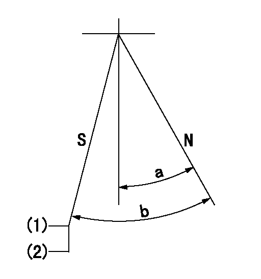
N:Engine normal (pump normal)
S:Engine stop
(1)Set the stopper screw.
(2)(Apply red paint after setting.)
----------
----------
a=20deg+-5deg b=(28deg)+-5deg
----------
----------
a=20deg+-5deg b=(28deg)+-5deg
0000001501 LEVER
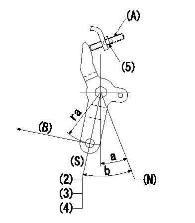
(N) Engine normal (pump normal)
(S) Engine stop
(A) stopper screw
(B) Stop direction (perpendicular)
Stop lever adjusting procedure
(1)After completing adjustment, confirm that the engine's normal lever angle (pump's normal lever) is within the specifications in the figure above.
(2)With the speed lever at Full and the pump speed at Na (specified speed), temporarily set the stopper screw (A) at the rack position Ra.
(3)Turn the stopper screw (A) Rb in the stop direction (Nb turns) and set it. Measure the rack position. (Rack position = approx. Rc)
(4)After setting, confirm non-injection with the speed lever at idle and pump speed at Nc.
(5)After adjustment, apply red paint.
----------
Na=1750r/min Ra=5.7mm Rb=1.5mm Nb=1.5 Rc=3.7mm Nc=250r/min
----------
ra=37mm a=20deg+-5deg b=(28deg)+-5deg
----------
Na=1750r/min Ra=5.7mm Rb=1.5mm Nb=1.5 Rc=3.7mm Nc=250r/min
----------
ra=37mm a=20deg+-5deg b=(28deg)+-5deg
Timing setting

(1)Pump vertical direction
(2)Position of gear's standard threaded hole at No 1 cylinder's beginning of injection
(3)-
(4)-
----------
----------
a=(70deg)
----------
----------
a=(70deg)
Information:
Battery
Never disconnect any charging unit circuit or battery circuit cable from battery when the charging unit is operated. A spark can cause an explosion from the flammable vapor mixture of hydrogen and oxygen that is released from the electrolyte through the battery outlets. Injury to personnel can be the result.
Before any testing is done on the electrical system, the batteries should be checked for good connections and must be at least 75% (1.225 Sp Gr) fully charged.The battery circuit is an electrical load on the charging unit. The load is variable because of the condition of the charge in the battery. Damage to the charging unit will result if the connections (either positive or negative) between the battery and charging unit are broken while the charging unit is in operation. This is because the battery load is lost and there is an increase in charging voltage. High voltage will damage, not only the charging unit, but also the regulator and other electrical components.Use the 4C4911 Battery Load Tester to load test a battery that does not hold a charge when in use. Refer to Operating Manual, Form No. SEHS9249 for more detailed instructions on use of the 4C4911 Battery Load Tester. See Special Instruction, Form No. SEHS7633 for the correct procedure and specifications to use when testing batteries.Charging System
The condition of charge in the battery at each regular inspection will show if the charging system operates correctly. An adjustment is necessary when the battery is constantly in a low condition of charge or a large amount of water is needed (more than one ounce of water per cell per week or per every 100 service hours).When it is possible, make a test of the charging unit and voltage regulator on the engine, and use wiring and components that are a permanent part of the system. Off-engine (bench) testing will give a test of the charging unit and voltage regulator operation. This testing will give an indication of needed repair. After repairs are made, again make a test to give proof that the units are repaired to their original condition of operation.To check for correct output of the alternator, see the Specifications module.For complete service information, refer to Service Manual Module, Form No. SENR3862, Delco Remy 27-SI Series Alternators. This module is part of REG00636 Service Manual.Before the start of on-engine testing, the charging system and battery must be checked as shown in the Steps that follow:1. Battery must be at least 75% (1.225 Sp.Gr.) fully charged and held tightly in place. The Battery holder must not put too much stress on the battery.2. Cables between the battery, starter and engine ground must be the correct size. Wires and cables must be free of corrosion and have cable support clamps to prevent stress on battery connections (terminals).3. Leads, junctions, switches, and panel instruments that have direct relation to the charging circuit must give correct circuit control.4. Inspect the drive components for the charging unit to be sure they are
Have questions with 101601-5262?
Group cross 101601-5262 ZEXEL
Hino
Hino
Hino
Hino
Hino
101601-5262
9 400 614 606
220005321A
INJECTION-PUMP ASSEMBLY
W06E
W06E