Information injection-pump assembly
ZEXEL
101601-5230
1016015230
HINO
220005330A
220005330a
Rating:
Service parts 101601-5230 INJECTION-PUMP ASSEMBLY:
1.
_
6.
COUPLING PLATE
7.
COUPLING PLATE
8.
_
9.
_
11.
Nozzle and Holder
23600-1843
12.
Open Pre:MPa(Kqf/cm2)
14.7{150}/19.6{200}
15.
NOZZLE SET
Cross reference number
ZEXEL
101601-5230
1016015230
HINO
220005330A
220005330a
Zexel num
Bosch num
Firm num
Name
Calibration Data:
Adjustment conditions
Test oil
1404 Test oil ISO4113 or {SAEJ967d}
1404 Test oil ISO4113 or {SAEJ967d}
Test oil temperature
degC
40
40
45
Nozzle and nozzle holder
105780-8140
Bosch type code
EF8511/9A
Nozzle
105780-0000
Bosch type code
DN12SD12T
Nozzle holder
105780-2080
Bosch type code
EF8511/9
Opening pressure
MPa
17.2
Opening pressure
kgf/cm2
175
Injection pipe
Outer diameter - inner diameter - length (mm) mm 6-2-600
Outer diameter - inner diameter - length (mm) mm 6-2-600
Overflow valve
131424-5720
Overflow valve opening pressure
kPa
255
221
289
Overflow valve opening pressure
kgf/cm2
2.6
2.25
2.95
Tester oil delivery pressure
kPa
157
157
157
Tester oil delivery pressure
kgf/cm2
1.6
1.6
1.6
Direction of rotation (viewed from drive side)
Right R
Right R
Injection timing adjustment
Direction of rotation (viewed from drive side)
Right R
Right R
Injection order
1-4-2-6-
3-5
Pre-stroke
mm
3.1
3.07
3.13
Beginning of injection position
Drive side NO.1
Drive side NO.1
Difference between angles 1
Cal 1-4 deg. 60 59.75 60.25
Cal 1-4 deg. 60 59.75 60.25
Difference between angles 2
Cyl.1-2 deg. 120 119.75 120.25
Cyl.1-2 deg. 120 119.75 120.25
Difference between angles 3
Cal 1-6 deg. 180 179.75 180.25
Cal 1-6 deg. 180 179.75 180.25
Difference between angles 4
Cal 1-3 deg. 240 239.75 240.25
Cal 1-3 deg. 240 239.75 240.25
Difference between angles 5
Cal 1-5 deg. 300 299.75 300.25
Cal 1-5 deg. 300 299.75 300.25
Injection quantity adjustment
Adjusting point
-
Rack position
9.6
Pump speed
r/min
900
900
900
Average injection quantity
mm3/st.
57.9
55.9
59.9
Max. variation between cylinders
%
0
-3.5
3.5
Basic
*
Fixing the rack
*
Standard for adjustment of the maximum variation between cylinders
*
Injection quantity adjustment_02
Adjusting point
H
Rack position
7.8+-0.5
Pump speed
r/min
250
250
250
Average injection quantity
mm3/st.
5.3
3.8
6.8
Max. variation between cylinders
%
0
-10
10
Fixing the rack
*
Standard for adjustment of the maximum variation between cylinders
*
Injection quantity adjustment_03
Adjusting point
A
Rack position
R1(9.6)
Pump speed
r/min
900
900
900
Average injection quantity
mm3/st.
57.9
56.9
58.9
Basic
*
Fixing the lever
*
Injection quantity adjustment_04
Adjusting point
B
Rack position
R1(9.6)
Pump speed
r/min
1500
1500
1500
Average injection quantity
mm3/st.
63.9
59.9
67.9
Fixing the lever
*
Injection quantity adjustment_05
Adjusting point
C
Rack position
R1-0.25
Pump speed
r/min
600
600
600
Average injection quantity
mm3/st.
40.3
36.3
44.3
Fixing the lever
*
Injection quantity adjustment_06
Adjusting point
D
Rack position
R1(9.6)
Pump speed
r/min
1200
1200
1200
Average injection quantity
mm3/st.
63.7
59.7
67.7
Fixing the lever
*
Injection quantity adjustment_07
Adjusting point
E
Rack position
R1+0.45
Pump speed
r/min
400
400
400
Average injection quantity
mm3/st.
39.9
35.9
43.9
Fixing the lever
*
Injection quantity adjustment_08
Adjusting point
I
Rack position
14.5+-0.
5
Pump speed
r/min
100
100
100
Average injection quantity
mm3/st.
108
108
118
Fixing the lever
*
Rack limit
*
Timer adjustment
Pump speed
r/min
1200+50
Advance angle
deg.
0
0
0
Remarks
Start
Start
Timer adjustment_02
Pump speed
r/min
1500
Advance angle
deg.
4.5
4.2
4.8
Remarks
Finish
Finish
Test data Ex:
Governor adjustment
N:Pump speed
R:Rack position (mm)
(1)Torque cam stamping: T1
(2)RACK LIMIT
----------
T1=C02
----------
----------
T1=C02
----------
Speed control lever angle

F:Full speed
I:Idle
(1)Stopper bolt set position 'H'
----------
----------
a=37deg+-5deg b=44deg+-3deg
----------
----------
a=37deg+-5deg b=44deg+-3deg
Stop lever angle
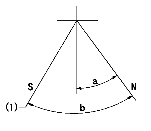
N:Engine normal (pump normal)
S:Engine stop
(1)Set the stopper screw. (After setting, apply red paint.)
----------
----------
a=20deg+-5deg b=(28deg)+-5deg
----------
----------
a=20deg+-5deg b=(28deg)+-5deg
Timing setting

(1)Pump vertical direction
(2)Position of gear's standard threaded hole at No 1 cylinder's beginning of injection
(3)-
(4)-
----------
----------
a=(70deg)
----------
----------
a=(70deg)
Information:
(1) Bore in rocker arm for shaft ... 24.803 0.013 mm (.9765 .0005 in) Diameter of rocker arm shaft ... 24.752 0.013 mm (.9745 .0005 in)(2) Put 5P3931 Anti-Seize Compound on all the threads of bolts that hold rocker arm shafts and tighten the bolts in the step sequence that follows:Step 1. Tighten bolts from 1 through 6 in number sequence to ... 270 27 N m (200 20 lb ft)Step 2. Tighten bolts from 1 through 6 in number sequence to ... 450 20 N m (330 15 lb ft)Step 3. Tighten bolts from 1 through 6 in number sequence again to ... 450 20 N m (330 15 lb ft) (3) Torque for locknut for valve adjustment screw ... 30 4 N m (22 3 lb ft)(4) Torque for locknut for bridge adjustment screw ... 30 4 N m (22 3 lb ft)(5) Valve lash: Intake valves ... 0.38 mm (.015 in)Exhaust valves ... 0.76 mm (.030 in)(6) Height to top of dowel ... 53.3 0.5 mm (2.10 .02 in)(7) Diameter of dowel ... 11.008 0.003 mm (.4334 .0001 in) Bore in bridge for dowel ... 11.13 0.05 mm (.438 .002 in)Bore in head for dowel ... 10.968 0.020 mm (.4318 .0008 in)(8) Diameter of valve lifter ... 27.896 0.013 mm (1.0983 .0005 in) Bore in block for valve lifter ... 27.953 0.019 mm (1.1005 .0008 in) See Guideline For Reusable Parts; Salvage Of Lifter Bores In 3400 Family Engines, Form No. SEBF8069 for the procedure, tooling and specifications needed to install 4W4588 Sleeves for salvage of the lifter bores in the cylinder block.(9) Guide springs must not be used again. Always install new guide springs. (10) 2N7229 Spring: Length under test force ... 74.2 mm (2.92 in)Test force ... 45 to 53 N (10 to 12 lb)Free length after test ... 114.3 mm (4.50 in)Outside diameter ... 29.7 mm (1.17 in)(11) Dowel length above top surface of rocker shaft support to be ... 12.7 1.0 mm (.50 .04 in)(12) Clearance for rocker arms (both ends) ... 0.30 to 1.40 mm (.012 to .055 in)(13) Use 2N7228 Washer as needed to get clearance (12). There must be a minimum of one 2N7228 Washer at each end of the rocker arm shaft. The bridge should be checked and/or adjusted each time the valves are adjusted. To check for wear use a dial indicator to measure the amount of wear on the bridge seat. Make sure the contact point on the dial indicator is small enough in diameter to get an accurate measurement. (A) Minimum dimension after reconditioning ... 16.51 mm (.650 in)(B) Allowable wear before reconditioning ... 0.13 mm (.005 in).Inspect the bridge seats for wear. Use the bridge again if the wear is 0.13 mm (.005 in) or less. When the wear seat is worn more than the