Information injection-pump assembly
BOSCH
9 400 614 604
9400614604
ZEXEL
101601-5222
1016015222
HINO
220005290A
220005290a
Rating:
Service parts 101601-5222 INJECTION-PUMP ASSEMBLY:
1.
_
6.
COUPLING PLATE
7.
COUPLING PLATE
8.
_
9.
_
11.
Nozzle and Holder
12.
Open Pre:MPa(Kqf/cm2)
21.6(220)
15.
NOZZLE SET
Cross reference number
BOSCH
9 400 614 604
9400614604
ZEXEL
101601-5222
1016015222
HINO
220005290A
220005290a
Zexel num
Bosch num
Firm num
Name
101601-5222
9 400 614 604
220005290A HINO
INJECTION-PUMP ASSEMBLY
W06E * K
W06E * K
Calibration Data:
Adjustment conditions
Test oil
1404 Test oil ISO4113 or {SAEJ967d}
1404 Test oil ISO4113 or {SAEJ967d}
Test oil temperature
degC
40
40
45
Nozzle and nozzle holder
105780-8140
Bosch type code
EF8511/9A
Nozzle
105780-0000
Bosch type code
DN12SD12T
Nozzle holder
105780-2080
Bosch type code
EF8511/9
Opening pressure
MPa
17.2
Opening pressure
kgf/cm2
175
Injection pipe
Outer diameter - inner diameter - length (mm) mm 6-2-600
Outer diameter - inner diameter - length (mm) mm 6-2-600
Overflow valve
131424-5720
Overflow valve opening pressure
kPa
255
221
289
Overflow valve opening pressure
kgf/cm2
2.6
2.25
2.95
Tester oil delivery pressure
kPa
157
157
157
Tester oil delivery pressure
kgf/cm2
1.6
1.6
1.6
Direction of rotation (viewed from drive side)
Right R
Right R
Injection timing adjustment
Direction of rotation (viewed from drive side)
Right R
Right R
Injection order
1-4-2-6-
3-5
Pre-stroke
mm
3.1
3.07
3.13
Beginning of injection position
Drive side NO.1
Drive side NO.1
Difference between angles 1
Cal 1-4 deg. 60 59.75 60.25
Cal 1-4 deg. 60 59.75 60.25
Difference between angles 2
Cyl.1-2 deg. 120 119.75 120.25
Cyl.1-2 deg. 120 119.75 120.25
Difference between angles 3
Cal 1-6 deg. 180 179.75 180.25
Cal 1-6 deg. 180 179.75 180.25
Difference between angles 4
Cal 1-3 deg. 240 239.75 240.25
Cal 1-3 deg. 240 239.75 240.25
Difference between angles 5
Cal 1-5 deg. 300 299.75 300.25
Cal 1-5 deg. 300 299.75 300.25
Injection quantity adjustment
Adjusting point
-
Rack position
9.5
Pump speed
r/min
900
900
900
Average injection quantity
mm3/st.
60.2
58.2
62.2
Max. variation between cylinders
%
0
-3.5
3.5
Basic
*
Fixing the rack
*
Standard for adjustment of the maximum variation between cylinders
*
Injection quantity adjustment_02
Adjusting point
H
Rack position
8+-0.5
Pump speed
r/min
250
250
250
Average injection quantity
mm3/st.
6.8
5.3
8.3
Max. variation between cylinders
%
0
-10
10
Fixing the rack
*
Standard for adjustment of the maximum variation between cylinders
*
Injection quantity adjustment_03
Adjusting point
A
Rack position
R1(9.5)
Pump speed
r/min
900
900
900
Average injection quantity
mm3/st.
60.2
59.2
61.2
Basic
*
Fixing the lever
*
Injection quantity adjustment_04
Adjusting point
B
Rack position
R1+0.1
Pump speed
r/min
1500
1500
1500
Average injection quantity
mm3/st.
67.3
63.3
71.3
Fixing the lever
*
Injection quantity adjustment_05
Adjusting point
C
Rack position
R1-0.45
Pump speed
r/min
600
600
600
Average injection quantity
mm3/st.
37.9
33.9
41.9
Fixing the lever
*
Injection quantity adjustment_06
Adjusting point
D
Rack position
R1+0.15
Pump speed
r/min
1200
1200
1200
Average injection quantity
mm3/st.
67.8
63.8
71.8
Fixing the lever
*
Injection quantity adjustment_07
Adjusting point
E
Rack position
R1(9.5)
Pump speed
r/min
400
400
400
Average injection quantity
mm3/st.
32.9
28.9
36.9
Fixing the lever
*
Injection quantity adjustment_08
Adjusting point
I
Rack position
-
Pump speed
r/min
100
100
100
Average injection quantity
mm3/st.
99
99
109
Fixing the lever
*
Rack limit
*
Timer adjustment
Pump speed
r/min
1000+50
Advance angle
deg.
0
0
0
Remarks
Start
Start
Timer adjustment_02
Pump speed
r/min
1500
Advance angle
deg.
3.5
3.2
3.8
Remarks
Finish
Finish
Test data Ex:
Governor adjustment
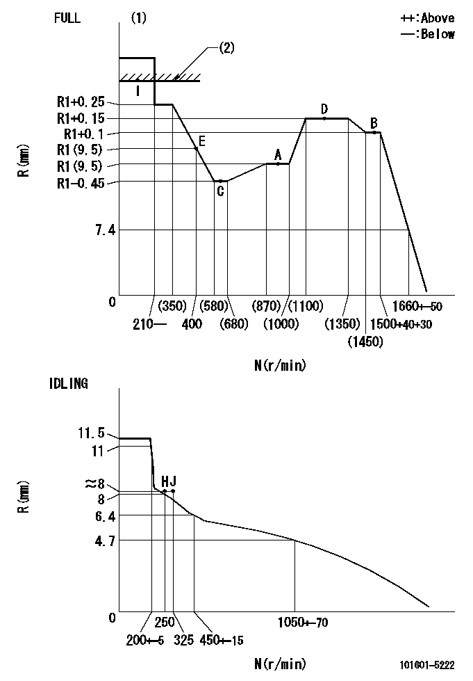
N:Pump speed
R:Rack position (mm)
(1)Torque cam stamping: T1
(2)RACK LIMIT
----------
T1=C10
----------
----------
T1=C10
----------
Speed control lever angle

F:Full speed
I:Idle
(1)Stopper bolt set position 'H'
----------
----------
a=32deg+-3deg b=34deg+-5deg
----------
----------
a=32deg+-3deg b=34deg+-5deg
Stop lever angle
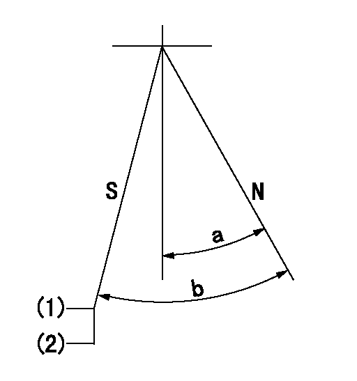
N:Engine normal (pump normal)
S:Engine stop
(1)Set the stopper screw.
(2)(Apply red paint after setting.)
----------
----------
a=20deg+-5deg b=(28deg)+-5deg
----------
----------
a=20deg+-5deg b=(28deg)+-5deg
0000001501 LEVER
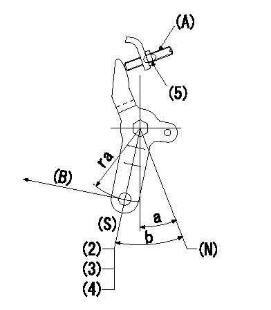
(N) Engine normal (pump normal)
(S) Engine stop
(A) stopper screw
(B) Stop direction (perpendicular)
Stop lever adjusting procedure
(1)After completing adjustment, confirm that the engine's normal lever angle (pump's normal lever) is within the specifications in the figure above.
(2)With the speed lever at Full and the pump speed at Na (specified speed), temporarily set the stopper screw (A) at the rack position Ra.
(3)Turn the stopper screw (A) Rb in the stop direction (Nb turns) and set it. Measure the rack position. (Rack position = approx. Rc)
(4)After setting, confirm non-injection with the speed lever at idle and pump speed at Nc.
(5)After adjustment, apply red paint.
----------
Na=1500r/min Ra=5.1mm Rb=1.5mm Nb=1.5 Rc=3.1mm Nc=250r/min
----------
ra=37mm a=20deg+-5deg b=(28deg)+-5deg
----------
Na=1500r/min Ra=5.1mm Rb=1.5mm Nb=1.5 Rc=3.1mm Nc=250r/min
----------
ra=37mm a=20deg+-5deg b=(28deg)+-5deg
Timing setting

(1)Pump vertical direction
(2)Position of gear's standard threaded hole at No 1 cylinder's beginning of injection
(3)-
(4)-
----------
----------
a=(70deg)
----------
----------
a=(70deg)
Information:
Guidelines For Reusable Parts; Valves And Valve Springs, Forms SEBF8002 and SEBF8034 have the procedure and specifications necessary for checking used valves and valve springs.(1) 4W2471 Spring for valves (outer) (new): Length under test force ... 53.24 mm (2.096 in)Test force ... 245 24 N (55 5 lb)Use again minimum load at length under test force ... 211 N (48 lb)Length of spring at valve open position ... 39.0 mm (1.54 in)Use again minimum load at valve open position ... 755 N (170 lb)Free length after test ... 59.5 mm (2.34 in)Outside diameter ... 37.31 mm (1.469 in)Spring must not be bent more than ... 2.10 mm (.083 in)(1) 4W2472 Spring for valves (inner) (new): Length under test force ... 50.24 mm (1.978 in)Test force ... 178 18 N (40 4 lb)Use again minimum load at length under test force ... 155 N (35 lb)Length of spring at valve open position ... 36.0 mm (1.42 in)Use again minimum load at valve open position ... 321 N (72 lb)Free length after test ... 65.7 mm (2.60 in)Outside diameter ... 25.13 mm (.989 in)Spring must not be bent more than ... 2.30 mm (.091 in)(1) 9Y3326 Spring for valves (outer) (new): Length under test force ... 53.24 mm (2.096 in)Test force ... 521 52 N (117 12 lb)Use again minimum load at length under test force ... 448 N (101 lb)Length of spring at valve open position ... 39.0 mm (1.54 in)Use again minimum load at valve open position ... 923 N (208 lb)Free length after test ... 69.04 mm (2.718 in)Outside diameter ... 42.61 mm (1.678 in)(1) 9Y3327 Spring for valves (inner) (new): Length under test force ... 50.42 mm (1.985 in)Test force ... 264 26 N (59 6 lb)Use again minimum load at length under test force ... 227 N (51 lb)Length of spring at valve open position ... 36 mm (1.4 in)Use again minimum load at valve open position ... 414 N (93 lb)Free length after test ... 70.8 mm (2.79 in)Outside diameter ... 30.0 mm (1.18 in)Spring must not be bent more than ... 2.10 mm (.083 in)(2) Height to top of valve guide ... 32.3 0.8 mm (1.27 .03 in)(3) Diameter of valve stem (new) ... 9.441 0.008 mm (.3717 .0003 in)Use again minimum diameter of valve stems:1W3860 Exhaust ... 9.408 mm (.3704 in)2W2622 Intake ... 9.408 mm (.3704 in)Bore in valve guide with guide installed in the head (new) ... 9.487 0.025 mm (.3735 .0010 in)Use again dimension for valve guide bore ... 9.538 mm (.3755 in)(4) Diameter of valve head: Exhaust valve ... 41.81 0.13 mm (1.646 .005 in)Intake valve ... 44.98 0.13 mm (1.771 .005 in)(5) Angle of intake valve face ... 29 1/4 1/4°Angle of exhaust valve face ... 44 1/4 1/4° (6) Depth of bore in head for valve seat insert ... 13.01 0.35 mm (.512 .014
Have questions with 101601-5222?
Group cross 101601-5222 ZEXEL
Hino
Hino
Hino
101601-5222
9 400 614 604
220005290A
INJECTION-PUMP ASSEMBLY
W06E
W06E