Information injection-pump assembly
BOSCH
9 400 619 590
9400619590
ZEXEL
101601-5221
1016015221
Rating:
Service parts 101601-5221 INJECTION-PUMP ASSEMBLY:
1.
_
6.
COUPLING PLATE
7.
COUPLING PLATE
8.
_
9.
_
11.
Nozzle and Holder
12.
Open Pre:MPa(Kqf/cm2)
21.6{220}
15.
NOZZLE SET
Cross reference number
BOSCH
9 400 619 590
9400619590
ZEXEL
101601-5221
1016015221
Zexel num
Bosch num
Firm num
Name
Calibration Data:
Adjustment conditions
Test oil
1404 Test oil ISO4113 or {SAEJ967d}
1404 Test oil ISO4113 or {SAEJ967d}
Test oil temperature
degC
40
40
45
Nozzle and nozzle holder
105780-8140
Bosch type code
EF8511/9A
Nozzle
105780-0000
Bosch type code
DN12SD12T
Nozzle holder
105780-2080
Bosch type code
EF8511/9
Opening pressure
MPa
17.2
Opening pressure
kgf/cm2
175
Injection pipe
Outer diameter - inner diameter - length (mm) mm 6-2-600
Outer diameter - inner diameter - length (mm) mm 6-2-600
Overflow valve
131424-5720
Overflow valve opening pressure
kPa
255
221
289
Overflow valve opening pressure
kgf/cm2
2.6
2.25
2.95
Tester oil delivery pressure
kPa
157
157
157
Tester oil delivery pressure
kgf/cm2
1.6
1.6
1.6
Direction of rotation (viewed from drive side)
Right R
Right R
Injection timing adjustment
Direction of rotation (viewed from drive side)
Right R
Right R
Injection order
1-4-2-6-
3-5
Pre-stroke
mm
3.1
3.07
3.13
Beginning of injection position
Drive side NO.1
Drive side NO.1
Difference between angles 1
Cal 1-4 deg. 60 59.75 60.25
Cal 1-4 deg. 60 59.75 60.25
Difference between angles 2
Cyl.1-2 deg. 120 119.75 120.25
Cyl.1-2 deg. 120 119.75 120.25
Difference between angles 3
Cal 1-6 deg. 180 179.75 180.25
Cal 1-6 deg. 180 179.75 180.25
Difference between angles 4
Cal 1-3 deg. 240 239.75 240.25
Cal 1-3 deg. 240 239.75 240.25
Difference between angles 5
Cal 1-5 deg. 300 299.75 300.25
Cal 1-5 deg. 300 299.75 300.25
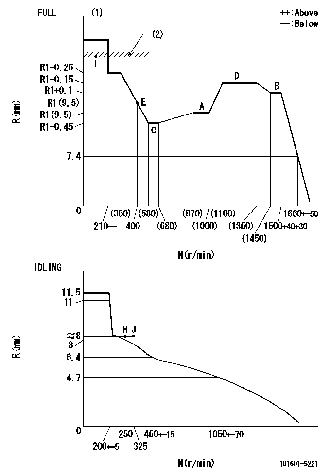
Injection quantity adjustment
Adjusting point
-
Rack position
9.5
Pump speed
r/min
900
900
900
Average injection quantity
mm3/st.
60.2
58.2
62.2
Max. variation between cylinders
%
0
-3.5
3.5
Basic
*
Fixing the rack
*
Standard for adjustment of the maximum variation between cylinders
*
Injection quantity adjustment_02
Adjusting point
H
Rack position
8+-0.5
Pump speed
r/min
250
250
250
Average injection quantity
mm3/st.
6.8
5.3
8.3
Max. variation between cylinders
%
0
-10
10
Fixing the rack
*
Standard for adjustment of the maximum variation between cylinders
*
Injection quantity adjustment_03
Adjusting point
A
Rack position
R1(9.5)
Pump speed
r/min
900
900
900
Average injection quantity
mm3/st.
60.2
59.2
61.2
Basic
*
Fixing the lever
*
Injection quantity adjustment_04
Adjusting point
B
Rack position
R1+0.1
Pump speed
r/min
1500
1500
1500
Average injection quantity
mm3/st.
67.3
63.3
71.3
Fixing the lever
*
Injection quantity adjustment_05
Adjusting point
C
Rack position
R1-0.45
Pump speed
r/min
600
600
600
Average injection quantity
mm3/st.
37.9
33.9
41.9
Fixing the lever
*
Injection quantity adjustment_06
Adjusting point
D
Rack position
R1+0.15
Pump speed
r/min
1200
1200
1200
Average injection quantity
mm3/st.
67.8
63.8
71.8
Fixing the lever
*
Injection quantity adjustment_07
Adjusting point
E
Rack position
R1(9.5)
Pump speed
r/min
400
400
400
Average injection quantity
mm3/st.
32.9
28.9
36.9
Fixing the lever
*
Injection quantity adjustment_08
Adjusting point
I
Rack position
-
Pump speed
r/min
100
100
100
Average injection quantity
mm3/st.
99
99
109
Fixing the lever
*
Rack limit
*
Timer adjustment
Pump speed
r/min
1000+50
Advance angle
deg.
0
0
0
Remarks
Start
Start
Timer adjustment_02
Pump speed
r/min
1500
Advance angle
deg.
3.5
3.2
3.8
Remarks
Finish
Finish
Test data Ex:
Governor adjustment
N:Pump speed
R:Rack position (mm)
(1)Torque cam stamping: T1
(2)RACK LIMIT
----------
T1=C10
----------
----------
T1=C10
----------
Speed control lever angle

F:Full speed
I:Idle
(1)Stopper bolt set position 'H'
----------
----------
a=32deg+-3deg b=34deg+-5deg
----------
----------
a=32deg+-3deg b=34deg+-5deg
Stop lever angle
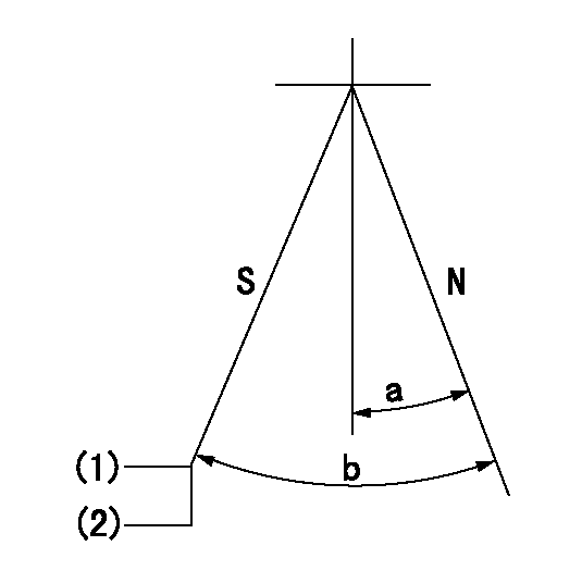
N:Engine normal (pump normal)
S:Engine stop
(1)Set the stopper screw. (After setting, apply red paint.)
(2)-
----------
----------
a=20deg+-5deg b=(28deg)+-5deg
----------
----------
a=20deg+-5deg b=(28deg)+-5deg
Timing setting

(1)Pump vertical direction
(2)Position of gear's standard threaded hole at No 1 cylinder's beginning of injection
(3)-
(4)-
----------
----------
a=(70deg)
----------
----------
a=(70deg)
Information:
(1) Maximum permissible temperature of the gear for installation on the camshaft (do not use a torch) ... 315°C (600°F)(2) Tight fit between the gear and camshaft ... 0.037 to 0.0123 mm (.0015 to .0048 in)(3) Diameter of the surfaces (journals) for the camshaft bearings (new) ... 69.850 0.013 mm (2.7500 .0005 in) Bore in front bearing for the camshaft (after assembly) ... 69.969 0.048 mm (2.7547 .0019 in)Bore in the other six bearings for the camshaft (after assembly) ... 69.982 0.061 mm (2.7552 .0024 in)(4) Thickness of thrust plate (new) ... 4.65 0.03 mm (.183 .001 in) End play of the camshaft ... 0.10 to 0.26 mm (.004 to .010 in) (5) Height of camshaft lobes.To find lobe height, use the procedure that follows:A. Measure camshaft lobe height (5).B. Measure base circle (7).C. Subtract base circle (STEP B) from lobe height (STEP A). The difference is actual lobe lift (6).D. Specified camshaft lobe lift (6) is:4W2430 Camshaft Assembly
a. Exhuast lobe ... 10.211 mm (.4020 in)b. Intake lobe ... 10.211 mm (.4020 in)7W3797 Camshaft Assembly
a. Exhaust lobe ... 10.210 mm (.4019 in)b. Intake lobe ... 10.212 mm (.4021 in)Maximum permissible difference between actual lobe lift (STEP C) and specified lobe lift (STEP D) is 0.13 mm (.005 in).Intake Valve Timing
1. Check the No. 1 intake valve lash with the engine stopped. The valve lash must be 0.30 to 0.46 mm (.012 to .018 in). If the valve lash is not in this range, adjust the lash to 0.38 mm (.015 in).2. Mark Top Center Position of the crankshaft on the vibration damper or pulley.3. Use a dial indicator to measure the intake valve movement.4. Rotate the crankshaft in the direction of normal engine rotation. Stop when the intake valve is 1.91 mm (.075 in) off its seat in the opening sequence.At this point the crankshaft Top Center Position Mark must be in position as follows: Engines with the 4W2430 Camshaft Assembly ... 7 2° After Top CenterEngines with the 7W3797 Camshaft Assembly ... 1 2° After Top CenterChecking Valve-Camshaft Timing (field procedure)
The following procedure will simplify the checking of the camshaft timing procedures.1. Set the No. 3 intake bridge adjustment.2. Set the No. 3 intake valve lash.3. Install the bolt in the flywheel with No. 1 piston at top center.4. Install the dial indicator (magnetic base) to No. 3 intake bridge.5. Remove the bolt from the flywheel.6. Set the gauge at zero and rotate the engine in the normal direction of operation (counterclockwise as seen from the flywheel end) until dial travel stops.The following chart indicates the correct setting.