Information injection-pump assembly
ZEXEL
101601-5201
1016015201
Rating:
Service parts 101601-5201 INJECTION-PUMP ASSEMBLY:
1.
_
6.
COUPLING PLATE
7.
COUPLING PLATE
8.
_
9.
_
11.
Nozzle and Holder
23600-1593A
12.
Open Pre:MPa(Kqf/cm2)
21.6{220}
15.
NOZZLE SET
Cross reference number
ZEXEL
101601-5201
1016015201
Zexel num
Bosch num
Firm num
Name
101601-5201
INJECTION-PUMP ASSEMBLY
14BE PE6A PE
14BE PE6A PE
Calibration Data:
Adjustment conditions
Test oil
1404 Test oil ISO4113 or {SAEJ967d}
1404 Test oil ISO4113 or {SAEJ967d}
Test oil temperature
degC
40
40
45
Nozzle and nozzle holder
105780-8140
Bosch type code
EF8511/9A
Nozzle
105780-0000
Bosch type code
DN12SD12T
Nozzle holder
105780-2080
Bosch type code
EF8511/9
Opening pressure
MPa
17.2
Opening pressure
kgf/cm2
175
Injection pipe
Outer diameter - inner diameter - length (mm) mm 6-2-600
Outer diameter - inner diameter - length (mm) mm 6-2-600
Overflow valve
131424-5720
Overflow valve opening pressure
kPa
255
221
289
Overflow valve opening pressure
kgf/cm2
2.6
2.25
2.95
Tester oil delivery pressure
kPa
157
157
157
Tester oil delivery pressure
kgf/cm2
1.6
1.6
1.6
Direction of rotation (viewed from drive side)
Right R
Right R
Injection timing adjustment
Direction of rotation (viewed from drive side)
Right R
Right R
Injection order
1-4-2-6-
3-5
Pre-stroke
mm
3.1
3.07
3.13
Beginning of injection position
Drive side NO.1
Drive side NO.1
Difference between angles 1
Cal 1-4 deg. 60 59.75 60.25
Cal 1-4 deg. 60 59.75 60.25
Difference between angles 2
Cyl.1-2 deg. 120 119.75 120.25
Cyl.1-2 deg. 120 119.75 120.25
Difference between angles 3
Cal 1-6 deg. 180 179.75 180.25
Cal 1-6 deg. 180 179.75 180.25
Difference between angles 4
Cal 1-3 deg. 240 239.75 240.25
Cal 1-3 deg. 240 239.75 240.25
Difference between angles 5
Cal 1-5 deg. 300 299.75 300.25
Cal 1-5 deg. 300 299.75 300.25
Injection quantity adjustment
Adjusting point
-
Rack position
9.2
Pump speed
r/min
900
900
900
Average injection quantity
mm3/st.
52.4
50.4
54.4
Max. variation between cylinders
%
0
-3.5
3.5
Basic
*
Fixing the rack
*
Standard for adjustment of the maximum variation between cylinders
*
Injection quantity adjustment_02
Adjusting point
H
Rack position
8+-0.5
Pump speed
r/min
250
250
250
Average injection quantity
mm3/st.
6.8
5.3
8.3
Max. variation between cylinders
%
0
-10
10
Fixing the rack
*
Standard for adjustment of the maximum variation between cylinders
*
Injection quantity adjustment_03
Adjusting point
A
Rack position
R1(9.2)
Pump speed
r/min
900
900
900
Average injection quantity
mm3/st.
52.4
51.4
53.4
Basic
*
Fixing the lever
*
Injection quantity adjustment_04
Adjusting point
B
Rack position
R1-0.35
Pump speed
r/min
1600
1600
1600
Average injection quantity
mm3/st.
50.2
46.2
54.2
Fixing the lever
*
Injection quantity adjustment_05
Adjusting point
C
Rack position
R1-0.35
Pump speed
r/min
600
600
600
Average injection quantity
mm3/st.
36.5
32.5
40.5
Fixing the lever
*
Injection quantity adjustment_06
Adjusting point
D
Rack position
R1-0.1
Pump speed
r/min
1200
1200
1200
Average injection quantity
mm3/st.
53.1
49.1
57.1
Fixing the lever
*
Injection quantity adjustment_07
Adjusting point
E
Rack position
R1+0.2
Pump speed
r/min
400
400
400
Average injection quantity
mm3/st.
29.2
25.2
33.2
Fixing the lever
*
Injection quantity adjustment_08
Adjusting point
I
Rack position
-
Pump speed
r/min
100
100
100
Average injection quantity
mm3/st.
99
99
109
Fixing the lever
*
Rack limit
*
Timer adjustment
Pump speed
r/min
1050--
Advance angle
deg.
0
0
0
Remarks
Start
Start
Timer adjustment_02
Pump speed
r/min
1000
Advance angle
deg.
0.3
Timer adjustment_03
Pump speed
r/min
1500
Advance angle
deg.
4.5
4.2
4.8
Remarks
Finish
Finish
Test data Ex:
Governor adjustment
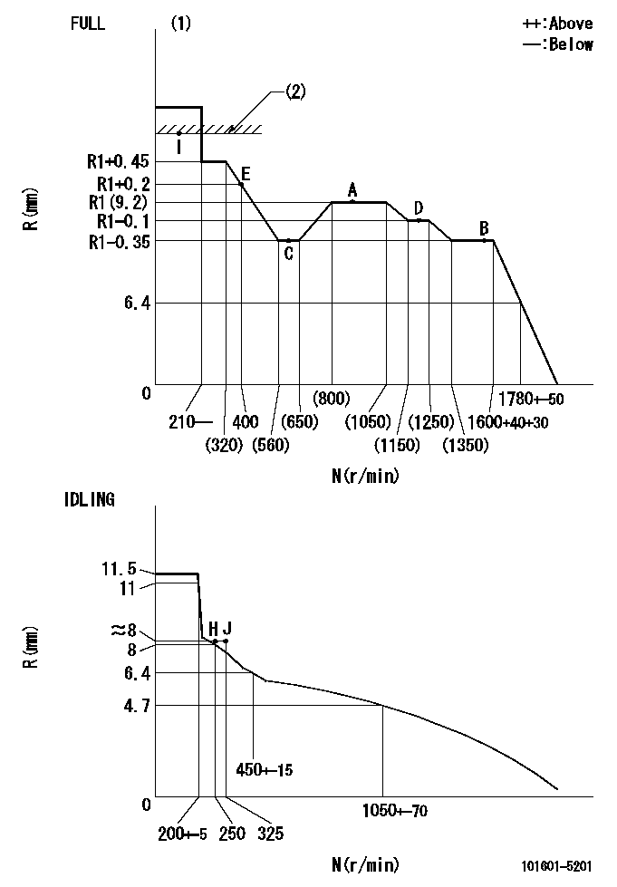
N:Pump speed
R:Rack position (mm)
(1)Torque cam stamping: T1
(2)RACK LIMIT
----------
T1=C09
----------
----------
T1=C09
----------
Speed control lever angle
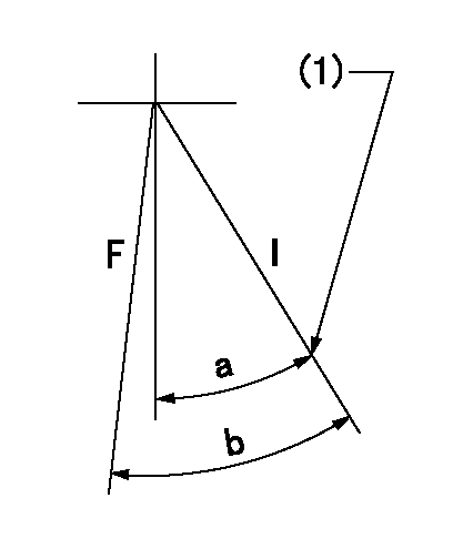
F:Full speed
I:Idle
(1)Stopper bolt set position 'H'
----------
----------
a=34deg+-5deg b=35deg+-3deg
----------
----------
a=34deg+-5deg b=35deg+-3deg
Stop lever angle
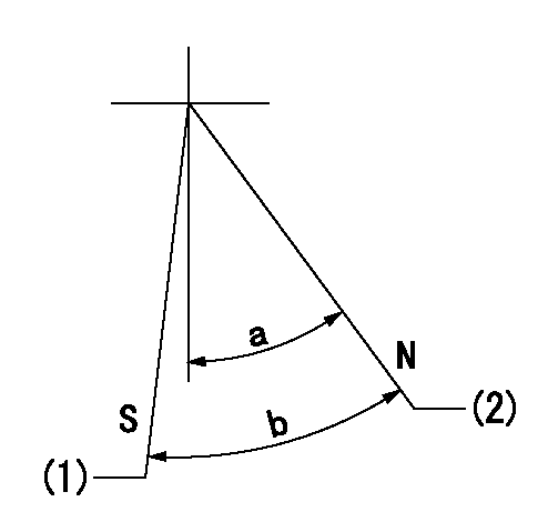
N:Engine normal (pump normal)
S:Engine stop
(1)Set the stopper screw. (After setting, apply red paint.)
(2)-
----------
----------
a=20deg+-5deg b=(28deg)+-5deg
----------
----------
a=20deg+-5deg b=(28deg)+-5deg
0000001501 LEVER
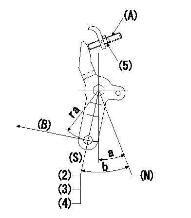
(N) Engine normal (pump normal)
(S) Engine stop
(A) stopper screw
(B) Stop direction (perpendicular)
Stop lever adjusting procedure
(1)After completing adjustment, confirm that the engine's normal lever angle (pump's normal lever) is within the specifications in the figure above.
(2)With the speed lever at Full and the pump speed at Na (specified speed), temporarily set the stopper screw (A) at the rack position Ra.
(3)Turn the stopper screw (A) Rb in the stop direction (Nb turns) and set it. Measure the rack position. (Rack position = approx. Rc)
(4)After setting, confirm non-injection with the speed lever at idle and pump speed at Nc.
(5)After adjustment, apply red paint.
----------
Na=1600r/min Ra=5.1mm Rb=1.5mm Nb=1.5 Rc=3.1mm Nc=250r/min
----------
ra=37mm a=20deg+-5deg b=(28deg)+-5deg
----------
Na=1600r/min Ra=5.1mm Rb=1.5mm Nb=1.5 Rc=3.1mm Nc=250r/min
----------
ra=37mm a=20deg+-5deg b=(28deg)+-5deg
Timing setting

(1)Pump vertical direction
(2)Position of gear's standard threaded hole at No 1 cylinder's beginning of injection
(3)-
(4)-
----------
----------
a=(70deg)
----------
----------
a=(70deg)
Information:
Start By:a. remove flywheel
Keep all parts clean from contaminants. Contaminants put into the system may cause rapid wear and shortened component life.
When a replacement of the rear seal is made, a replacement of the wear sleeve is to be made also. 1. Remove the crankshaft rear seal with tool (A). 2. Install tool (C) as shown.3. Install tool (B) between tool (C) and the wear sleeve. Turn tool (B) until the edge of the tool makes a flat place (crease) in the wear sleeve. Do this in two or more places until the wear sleeve in loose.4. Remove tool (C) and the wear sleeve by hand. The following steps are for the installation of the crankshaft rear seal and wear sleeve. 5. Install the crankshaft rear seal and wear sleeve with tooling (A) as follows:a. Put locator (1) in position on the crankshaft and install the three bolts that hold it in place.b. Put clean engine oil on the seal lip of seal (6) and on the outside diameter of wear sleeve (2).c. Install seal (6) on wear sleeve (2) from the end of the wear sleeve that has the bevel on the outside diameter. Make sure the lip of the seal is toward the inside of the engine and the bevel that is on the outside diameter of the wear sleeve is toward the outside of the engine when installed.d. Use 6V1541 Quick Cure Primer to clean the outside diameter of the crankshaft flange (3) and the inside diameter of wear sleeve (2).e. Put 9S3265 Retaining Compound on the outside diameter of crankshaft flange (3) and the inside diameter of wear sleeve (2). Make sure the lip of the seal is toward the inside of the engine and the outside diameter bevel of the wear sleeve is toward the outside of the engine.f. Put wear sleeve (2) with seal (6) on locator (1). Put installer (4) on locator (1) and install nut (5). Put lubrication on the face of the washer and the nut.g. Tighten nut (5) until installer (4) comes in contact with locator (1).h. Remove tooling (A) and check the wear sleeve and seal for correct installation.End By:a. install flywheel
Have questions with 101601-5201?
Group cross 101601-5201 ZEXEL
Hino
101601-5201
INJECTION-PUMP ASSEMBLY