Information injection-pump assembly
ZEXEL
101601-5190
1016015190
HINO
220005130A
220005130a
Rating:
Service parts 101601-5190 INJECTION-PUMP ASSEMBLY:
1.
_
6.
COUPLING PLATE
7.
COUPLING PLATE
8.
_
9.
_
11.
Nozzle and Holder
236001800A
12.
Open Pre:MPa(Kqf/cm2)
19.6(200)
15.
NOZZLE SET
Cross reference number
ZEXEL
101601-5190
1016015190
HINO
220005130A
220005130a
Zexel num
Bosch num
Firm num
Name
Calibration Data:
Adjustment conditions
Test oil
1404 Test oil ISO4113 or {SAEJ967d}
1404 Test oil ISO4113 or {SAEJ967d}
Test oil temperature
degC
40
40
45
Nozzle and nozzle holder
105780-8140
Bosch type code
EF8511/9A
Nozzle
105780-0000
Bosch type code
DN12SD12T
Nozzle holder
105780-2080
Bosch type code
EF8511/9
Opening pressure
MPa
17.2
Opening pressure
kgf/cm2
175
Injection pipe
Outer diameter - inner diameter - length (mm) mm 6-2-600
Outer diameter - inner diameter - length (mm) mm 6-2-600
Overflow valve
131424-5720
Overflow valve opening pressure
kPa
255
221
289
Overflow valve opening pressure
kgf/cm2
2.6
2.25
2.95
Tester oil delivery pressure
kPa
157
157
157
Tester oil delivery pressure
kgf/cm2
1.6
1.6
1.6
Direction of rotation (viewed from drive side)
Right R
Right R
Injection timing adjustment
Direction of rotation (viewed from drive side)
Right R
Right R
Injection order
1-4-2-6-
3-5
Pre-stroke
mm
3.1
3.07
3.13
Beginning of injection position
Drive side NO.1
Drive side NO.1
Difference between angles 1
Cal 1-4 deg. 60 59.75 60.25
Cal 1-4 deg. 60 59.75 60.25
Difference between angles 2
Cyl.1-2 deg. 120 119.75 120.25
Cyl.1-2 deg. 120 119.75 120.25
Difference between angles 3
Cal 1-6 deg. 180 179.75 180.25
Cal 1-6 deg. 180 179.75 180.25
Difference between angles 4
Cal 1-3 deg. 240 239.75 240.25
Cal 1-3 deg. 240 239.75 240.25
Difference between angles 5
Cal 1-5 deg. 300 299.75 300.25
Cal 1-5 deg. 300 299.75 300.25
Injection quantity adjustment
Adjusting point
-
Rack position
9.3
Pump speed
r/min
900
900
900
Average injection quantity
mm3/st.
56.4
54.4
58.4
Max. variation between cylinders
%
0
-3.5
3.5
Basic
*
Fixing the rack
*
Standard for adjustment of the maximum variation between cylinders
*
Injection quantity adjustment_02
Adjusting point
-
Rack position
8.6+-0.5
Pump speed
r/min
250
250
250
Average injection quantity
mm3/st.
9
7.5
10.5
Max. variation between cylinders
%
0
-10
10
Fixing the rack
*
Standard for adjustment of the maximum variation between cylinders
*
Remarks
Adjust only variation between cylinders; adjust governor according to governor specifications.
Adjust only variation between cylinders; adjust governor according to governor specifications.
Injection quantity adjustment_03
Adjusting point
A
Rack position
R1(9.3)
Pump speed
r/min
900
900
900
Average injection quantity
mm3/st.
56.4
55.4
57.4
Basic
*
Fixing the lever
*
Injection quantity adjustment_04
Adjusting point
B
Rack position
R1+0.1
Pump speed
r/min
1500
1500
1500
Average injection quantity
mm3/st.
64
60
68
Fixing the lever
*
Injection quantity adjustment_05
Adjusting point
C
Rack position
R1-0.55
Pump speed
r/min
600
600
600
Average injection quantity
mm3/st.
35.3
31.3
39.3
Fixing the lever
*
Injection quantity adjustment_06
Adjusting point
D
Rack position
R1+0.3
Pump speed
r/min
1200
1200
1200
Average injection quantity
mm3/st.
70.2
66.2
74.2
Fixing the lever
*
Injection quantity adjustment_07
Adjusting point
E
Rack position
R1(9.3)
Pump speed
r/min
400
400
400
Average injection quantity
mm3/st.
30
26
34
Fixing the lever
*
Injection quantity adjustment_08
Adjusting point
I
Rack position
-
Pump speed
r/min
100
100
100
Average injection quantity
mm3/st.
94
94
104
Fixing the lever
*
Rack limit
*
Timer adjustment
Pump speed
r/min
1200+50
Advance angle
deg.
0
0
0
Remarks
Start
Start
Timer adjustment_02
Pump speed
r/min
1500
Advance angle
deg.
4
3.7
4.3
Remarks
Finish
Finish
Test data Ex:
Governor adjustment
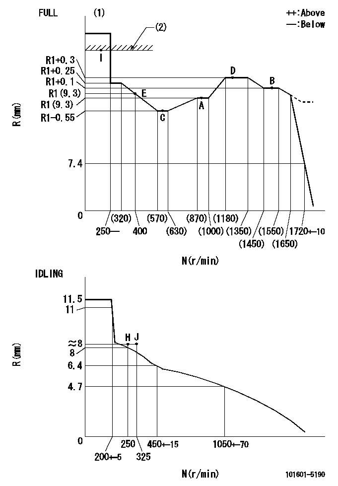
N:Pump speed
R:Rack position (mm)
(1)Torque cam stamping: T1
(2)RACK LIMIT
----------
T1=B92
----------
----------
T1=B92
----------
Speed control lever angle

F:Full speed
I:Idle
(1)Stopper bolt set position 'H'
----------
----------
a=34deg+-3deg b=34deg+-5deg
----------
----------
a=34deg+-3deg b=34deg+-5deg
Stop lever angle
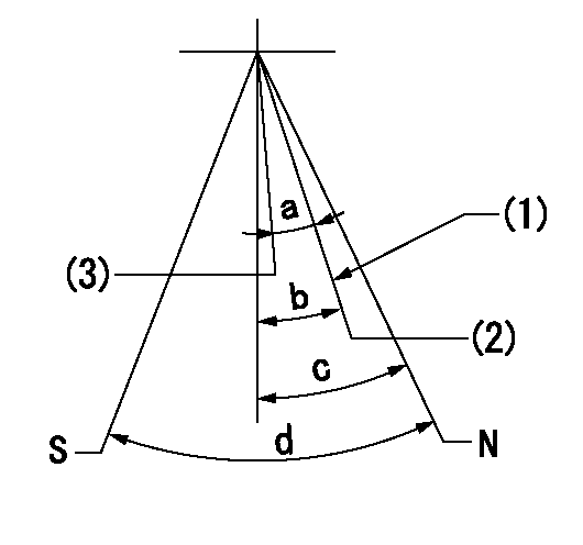
N:Pump normal
S:Stop the pump.
(1)Set the normal set bolt.
(2)Engine normal
(3)Engine stop
----------
----------
a=(12deg) b=(22deg)+-5deg c=35deg+-5deg d=40deg+-5deg
----------
----------
a=(12deg) b=(22deg)+-5deg c=35deg+-5deg d=40deg+-5deg
Timing setting

(1)Pump vertical direction
(2)Position of gear's standard threaded hole at No 1 cylinder's beginning of injection
(3)-
(4)-
----------
----------
a=(70deg)
----------
----------
a=(70deg)
Information:
Keep all parts clean from contaminants. Contaminants put into the system may cause rapid wear and shortened component life.
1. Turn the crankshaft until the "C" mark on the crankshaft gear is in alignment with the "C" mark on the camshaft gear. To keep the engine timing correct during removal and installation of the camshaft, put a mark on the teeth of the fuel injection pump drive gear and idler gear at location (A). Put a mark on the teeth of the idler gear and camshaft gear at location (B). When installing the camshaft, the engine timing will be correct when the marks at locations (A) and (B) are in alignment and the "C" marks on the crankshaft and camshaft gears are in alignment.2. Remove the bolts, lock and washer (1) that hold the camshaft in position.
Do not cause damage to the lobes or bearings when the camshaft is removed.
3. Remove the camshaft and gear (2).4. If necessary, remove the bolts and gear. The following steps are for the installation of the camshaft.5. Put the camshaft drive gear in position on the end of the camshaft, and install the bolts that hold it. Tighten the bolts to a torque of 55 7 N m (41 5 lb ft).
Do not cause damage to the lobes or bearings when the camshaft is installed.
6. Put 2P2506 Thread Lubricant on the camshaft lobes only, and clean engine oil on the bearing journals. Install camshaft (3) aligning the "C" marks and the marks put on the gears during removal.7. Install washer (1), the lock and bolts.End By:a. install valve liftersb. install timing gear cover